Air conditioning condensation drainage system

a drainage system and condensation technology, applied in the field of air conditioning condensation drainage system, can solve the problems of oxidizing the roofing membrane, affecting the efficiency of the cooling system, and increasing the detrimental effect of the roofing material on the roofing membrane, so as to effectively prepare the roofing system and minimize the amount of drain channel material

Inactive Publication Date: 2005-04-26
CROSSD HLDG +1
View PDF10 Cites 24 Cited by
  • Summary
  • Abstract
  • Description
  • Claims
  • Application Information

AI Technical Summary

Benefits of technology

[0019]It is another feature of the present invention to provide a novel a / c condensate drainage system for the roofing systems of buildings which includes the use of pre-manufactured surface drainage system materials that are designed for installation onto a roof membrane to create a non destructive path over the surface of a roofing system and will direct the discharge condensation from roof mounted a / c units to an in-roof drain or gutter;
[0021]It is also a feature of the present invention to provide a novel a / c condensate drainage system for the roofing systems of buildings which is of integral construction, being formed in any desired manner, such as by molding or extrusion, including molding or extrusion of materials onto a roofing membrane to define air-conditioning condensate drainage channels or collector basins. The materials may be cured in place on the roofing membrane or bonded or cemented to the primary roofing membrane of a roof to create one or more water drain channels for draining a / c condensate or water from any other source to drain openings or gutters, while protecting the primary roofing membrane from accelerated deterioration by the substantially continuous presence of water, including air-conditioning condensate or its constituents.
[0025]As a further alternative, an a / c drain channel may be formed on a roof membrane or on a drain channel membrane layer covering a roof membrane. In this case, strips of ridge defining material can be heat sealed, cemented, bonded or otherwise secured to the roof membrane or drain channel membrane layer and can be spaced as desired for defining a drain channel of desired width. Strips of ridge defining material of this nature can be applied to the roof membrane or a drain channel membrane in a manner defining one or more collector junctions or receptacles that are arranged to receive a / c condensate from two or more a / c drain channels to minimize the amount of drain channel material that might be required to effectively prepare a roofing system for a / c condensate drainage.

Problems solved by technology

Moreover, as water evaporation occurs and a / c condensation continues to be added onto the roofing membrane, the concentration of chemicals and heavy metals will continuously increase thus increasing the detrimental effect of these materials to the roofing membrane.
It has been found that summer heat will actually turn the water flows and pools into boiling water which will literally oxidize the roofing membrane.
Extreme cold will freeze these water flows and pools causing fissures in the roof membrane surface.
Present methods of removing the a / c condensation from the roof surface are not effective.
It has been found with condensate drainage piping that the piping systems quickly become clogged with debris and algae that is present within the drainage system, especially when the a / c unit is situated in a humid environment.
If the a / c unit structure is partially rusted away adjacent the perimeter of the condensate collection pan, which is often the case, significant leakage of condensate onto the roofing membrane will occur.
As typically occurs in roofing systems, having condensate drain conduits, because of traffic, age, and constant clogging problems requiring significant maintenance effort and expense, personnel having the responsibility for building maintenance will eventually disconnect the condensate drainage pipes from the air conditioning units.
The eventual result is that the disconnected a / c drainage pipes will end up as debris that is present on the roof surface.
This disconnected piping debris obviously presents a hazard to workers engaged in roofing maintenance and repair and can be a cause of damage to the roofing membrane.
While commercial buildings can be provided with internal a / c drain piping systems that extend throughout the building structure to conventional building drain lines, this internal piping method is seldom used because it is expensive and requires frequent maintenance.
Debris collected by the condensate of the a / c units will flow along with the condensate into the drain lines and in time will clog the lines.
The algae that builds up in all a / c drain lines also causes clogging of the lines.
In a relatively short time the drain lines will be sufficiently blocked that flow of condensate drainage will be blocked.
These systems are virtually always abandoned due to clogging because the drain lines, being located within the building structure are difficult to access and service or repair.
Even though the presence of a / c condensate on a roof membrane is known to cause damage to the roofing system, surface drainage is the method that is most often employed for condensate drainage.
In this case, persistent a / c condensation fluids are allowed to collect in certain areas on the roof membrane surface, causing extensive and accelerated roof membrane deterioration.

Method used


Image

  • Air conditioning condensation drainage system
  • Air conditioning condensation drainage system
  • Air conditioning condensation drainage system

Examples


Embodiment Construction

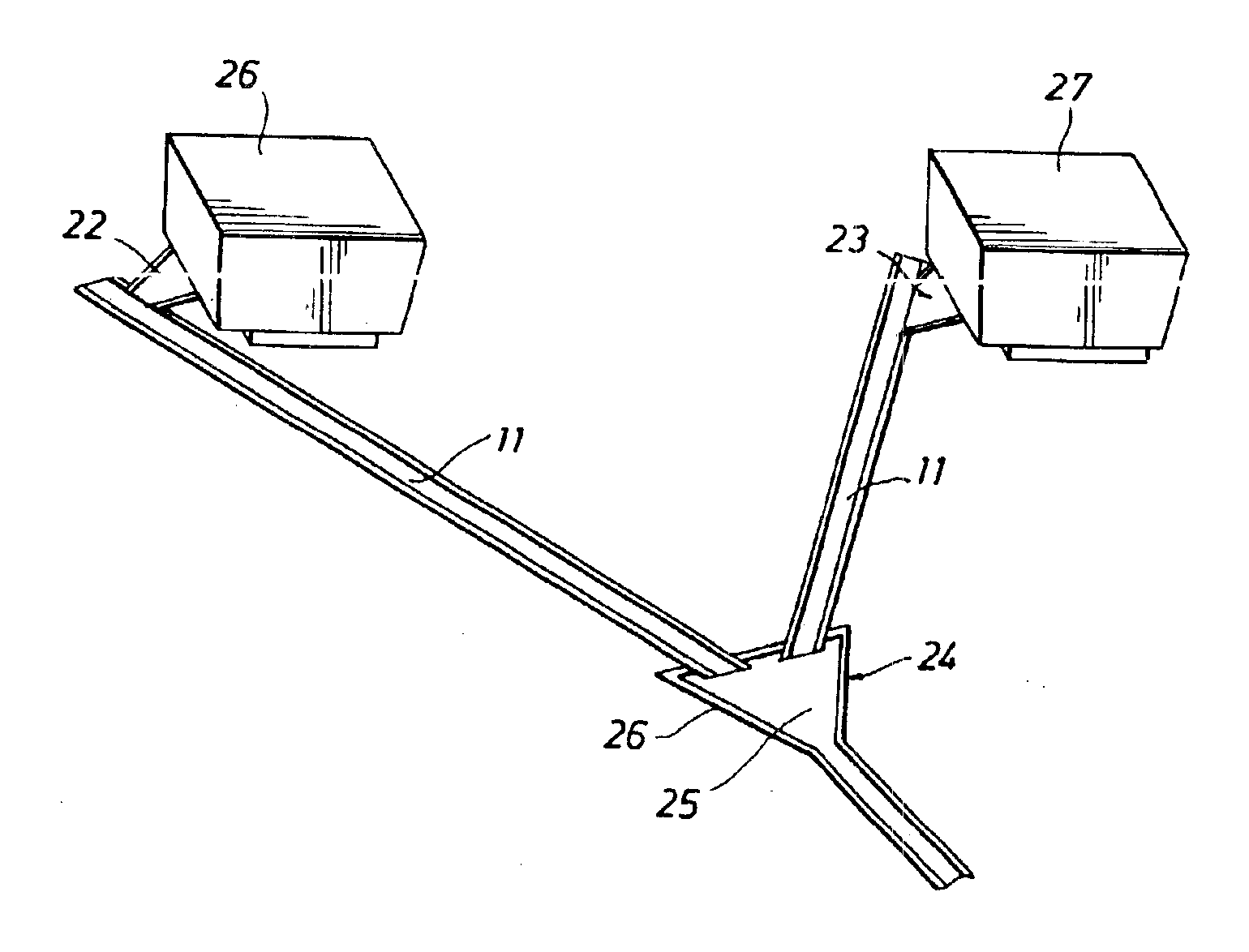
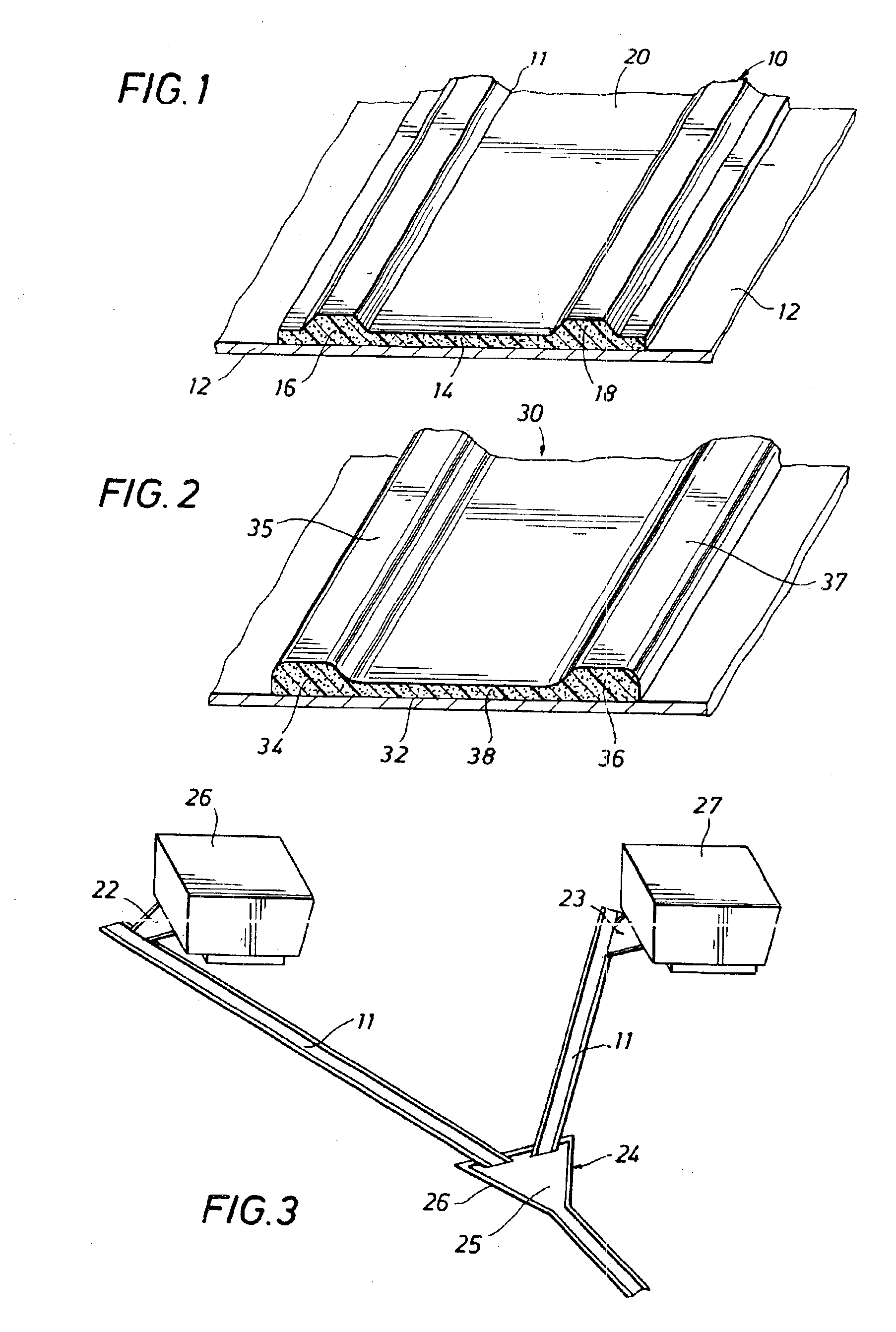
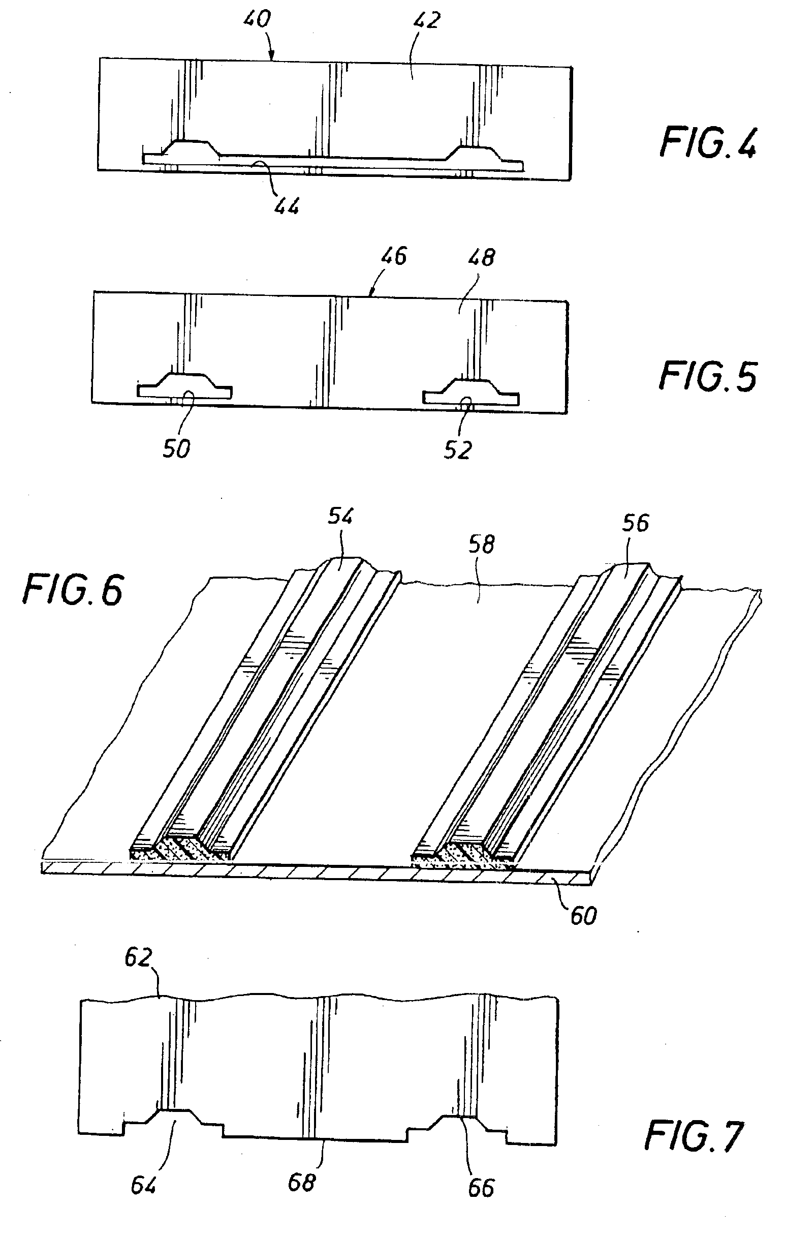
[0042]Referring now to the drawings and first to FIG. 1, an air-conditioning condensate drainage system constructed in accordance with the principles of the present invention and representing the preferred embodiment is shown generally at 10 and is shown in the figure as a partial strip of condensate drain structure which is shown to be mounted in any suitable fashion onto the roofing membrane 12 of a building roofing system. The air-conditioning condensate drainage system 10 comprises an isolation membrane 14 which is typically in the form of an elongate strip of material that is compatible with the membrane material of the roofing membrane 12. Preferably, the isolation membrane will be a component of an integral construction composed of a polymer material such as polyvinyl chloride (PVC) which may be layered with other suitable materials and may be reinforced by a suitable fabric to enhance the structural integrity thereof. The integral condensate drainage strip material 11 may be...


PUM


Abstract

An air-conditioning condensate drainage system for mounting to the roof membrane of the roof structure of buildings or for construction thereof directly onto the roof membrane of a building structure. The air-conditioning condensate drainage system is defined by one or more strips of material having an isolation membrane having a bottom surface for assembly to a roof membrane. A pair of spaced ridge elements project upwardly from the isolation membrane and cooperate with the isolation membrane to define an air-conditioning condensate drainage channel. In the alternative, ridge strips may be disposed in spaced relation and fixed directly to a roof membrane to define condensate drain channels along the roof membrane to in-roof drains. The condensate drain strip or ridge strips may be molded or extruded and maybe formed directly on and adhered to or fixed to the roof membrane to define the condensate drain channels.

Description

CROSS-REFERENCED TO RELATED PATENT[0001]The present invention concerns an improvement to the subject matter of U.S. Pat. No. 6,167,717 for “Air Conditioning Condensation Drainage System”, which issued to William E. Dudley and C. Ross Dutton on Jan. 2, 2001.BACKGROUND OF THE INVENTION[0002]1. Field of the Invention[0003]The present invention relates generally to the compromise or deterioration of roofing membrane materials by the condensate from air conditioning systems that are mounted on or above the roofs of commercial buildings that are finished with a roofing membrane that is slightly inclined or contoured, so as to direct water to drain openings in the roof and into drain conduits. More particularly, the present invention concerns the provision of a roof mounted drain system for collecting air conditioning condensate from roof-mounted air-conditioning units and conducting the condensate to a disposal drain and simultaneously isolating the roof membrane from contact by the air c...

Claims


Application Information

Patent Timeline
Patent Type & Authority Patents(United States)
IPC IPC(8): F24F13/22F24F13/00
CPCF24F13/222F24F2013/227
Inventor DUDLEY, WILLIAM E.DUTTON, C. ROSS
Owner CROSSD HLDG
Why Eureka
Try Eureka