System and methods for reducing interfacial porosity in cements

a technology of interfacial porosity and cement, which is applied in the field of system and methods for reducing interfacial porosity in cement, can solve the problems of structural failure and replacement, and achieve the effect of reducing pores

Inactive Publication Date: 2005-04-26
CAMBRIDGE POLYMER GROUP
View PDF20 Cites 71 Cited by
  • Summary
  • Abstract
  • Description
  • Claims
  • Application Information

AI Technical Summary

Benefits of technology

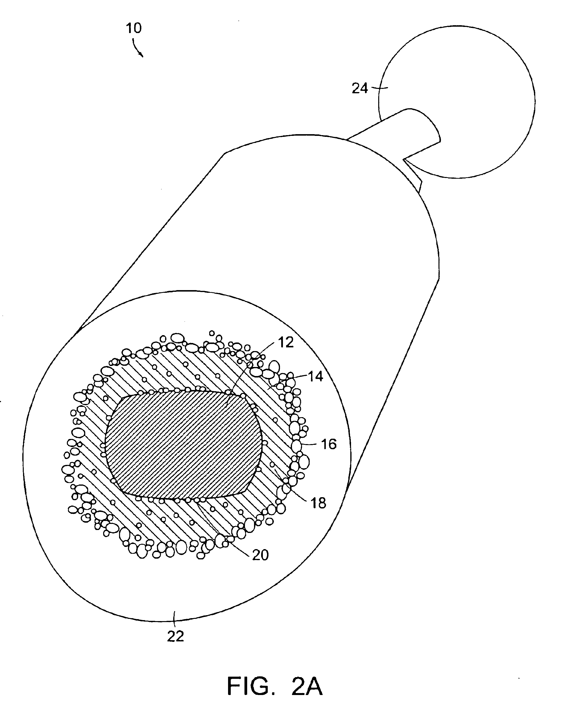
[0014]The present invention provides a system and a method for reducing pores, or air pockets, that form at the interface between the material used to attach or adhere the surface of a component, such as a prosthesis, to a site. The reduction of these interfacial pores reduces the likelihood of fracture of the material such as a cement mantle, which loosens the component, and ultimately may lead to failure of the structure and the need for replacement.
[0015]In a preferred embodiment of the invention the system and method of the present invention takes advantage of the shear-thinning properties of the partially-polymerized bone cement by vibrating the stem component as it is inserted into the bone cement, thereby reducing the viscosity locally at the cement-component interface. In another preferred embodiment of the invention the viscosity of the bone cement can be reduced by heating (or cooling) the stem component during insertion. In other preferred embodiments, the wetting of the stem component by the partially cured bone cement is enhanced by microchannels on the surface of the stem component or by other rough surface structures that increase surface area without increasing porosity.

Problems solved by technology

The reduction of these interfacial pores reduces the likelihood of fracture of the material such as a cement mantle, which loosens the component, and ultimately may lead to failure of the structure and the need for replacement.

Method used


Image

  • System and methods for reducing interfacial porosity in cements
  • System and methods for reducing interfacial porosity in cements
  • System and methods for reducing interfacial porosity in cements

Examples


example 1

[0101]The results demonstrate the different interfacial porosity obtained by superimposing oscillatory motion velocity at a single fixed frequency onto a relatively steady insertion. Briefly, the experimental protocol that is followed utilizes insertion of simulated hip stem components (glass test tubes) into Howmedica Surgical Simplex P® bone cement at a cure time of 6 minutes contained in cylindrical acrylic chambers (2.5 cm diameter, 7 cm deep).

[0102]The cement is hand mixed for 30 seconds and centrifuged for 30 seconds at high speed. The top 2-3 mm of cement is scraped away to remove bubbles that migrated during the centrifugation process prior to insertion of the model stems. Both the stems were inserted at an average velocity of 1 cm / sec; in addition, one stem is also oscillated during insertion at 100 rad / sec with an estimated amplitude of 150 microns (peak-to-peak). The cured cement / stem interface are observed and photographed using a light microscope with transmission illum...

example 2

[0105]The results demonstrate the difference interfacial porosity obtained by superposing oscillatory motion velocity at a single fixed frequency onto a slower relatively steady insertion. The experimental protocol that is in Example 1 is used, with an insertion at an average velocity of 0.25 cm / sec.

[0106]FIGS. 25A and 25B present light micrographs of the interface between the model stem and the cement. FIG. 25A illustrates the interface obtained after steady insertion at an average velocity of 0.25 cm / sec without oscillation. FIG. 25B illustrates the interface obtained after steady insertion at an average velocity of 1 cm / sec with an oscillation of 150 microns peak-to-peak amplitude and a frequency of 100 radians / second. Both images are relatively free of small scale pores. Again, larger scale structures (100-300 microns) seen in FIG. 25B appeared smeared with indistinct borders giving the general appearance of a more uniform interfacial cement layer.

[0107]After optical examination...

example 3

[0108]The results demonstrate the difference interfacial porosity obtained by superposing oscillatory motion velocity at a single fixed frequency relatively steady insertion with intermittent pauses. The experimental protocol that was in Example 1 was used, with an insertion at an average velocity of 0.25 cm / sec.

[0109]FIGS. 26A and 26B present light micrographs of the interface between the model stem and the cement. FIG. 26A illustrates the interface obtained after steady insertion at an average velocity of 0.25 cm / sec without oscillation. FIG. 26B illustrates the interface obtained after steady insertion at an average velocity of 1 cm / sec with an oscillation of 150 microns peak-to-peak amplitude and a frequency of 100 radians / second. Both images are relatively free of small scale pores. Again, larger scale structures (100-300 microns) seen in FIG. 26B appeared smeared with indistinct borders giving the general appearance of a more uniform interfacial cement layer.

[0110]After optica...


PUM

PropertyMeasurementUnit
diameteraaaaaaaaaa
diameteraaaaaaaaaa
insertion velocitiesaaaaaaaaaa

Abstract

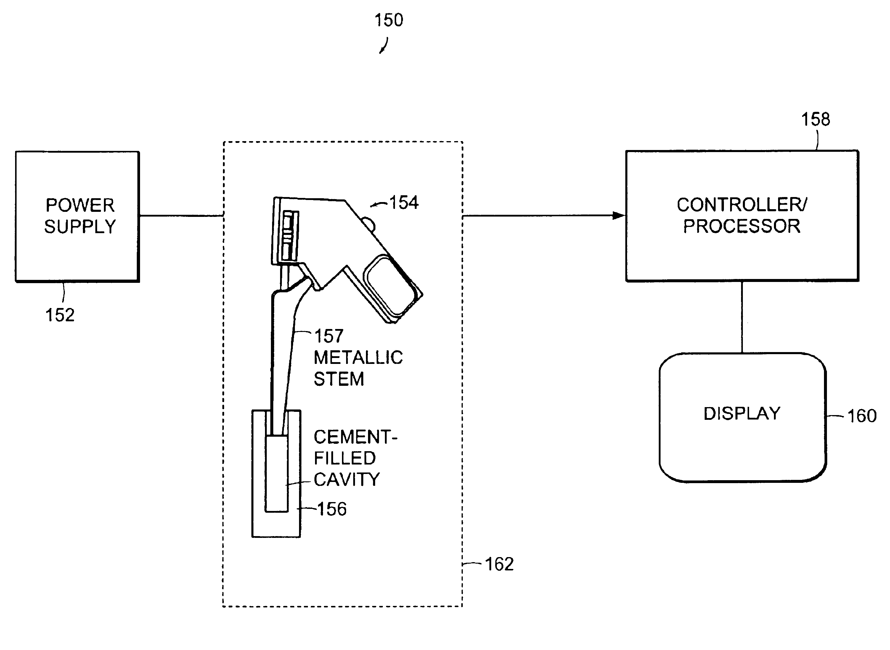
The present invention provides a system and a method for reducing pores, or air pockets, that form at the interface between the material used to attach or adhere the surface of a component, such as a prosthesis, to a site.A preferred embodiment of the invention includes an actuator that controls a coupler which transmits energy to a prosthesis being inserted into a material to reduce porosity at an interface between the prosthesis and the material.The system of the present invention can include an oscillating hand-held device that vibrates the stem component of an orthopedic prosthesis at a particular frequency and amplitude. The device is typically held by the hand of the surgeon, who guides the vibrating prosthesis into the cement-filled medullary cavity.

Description

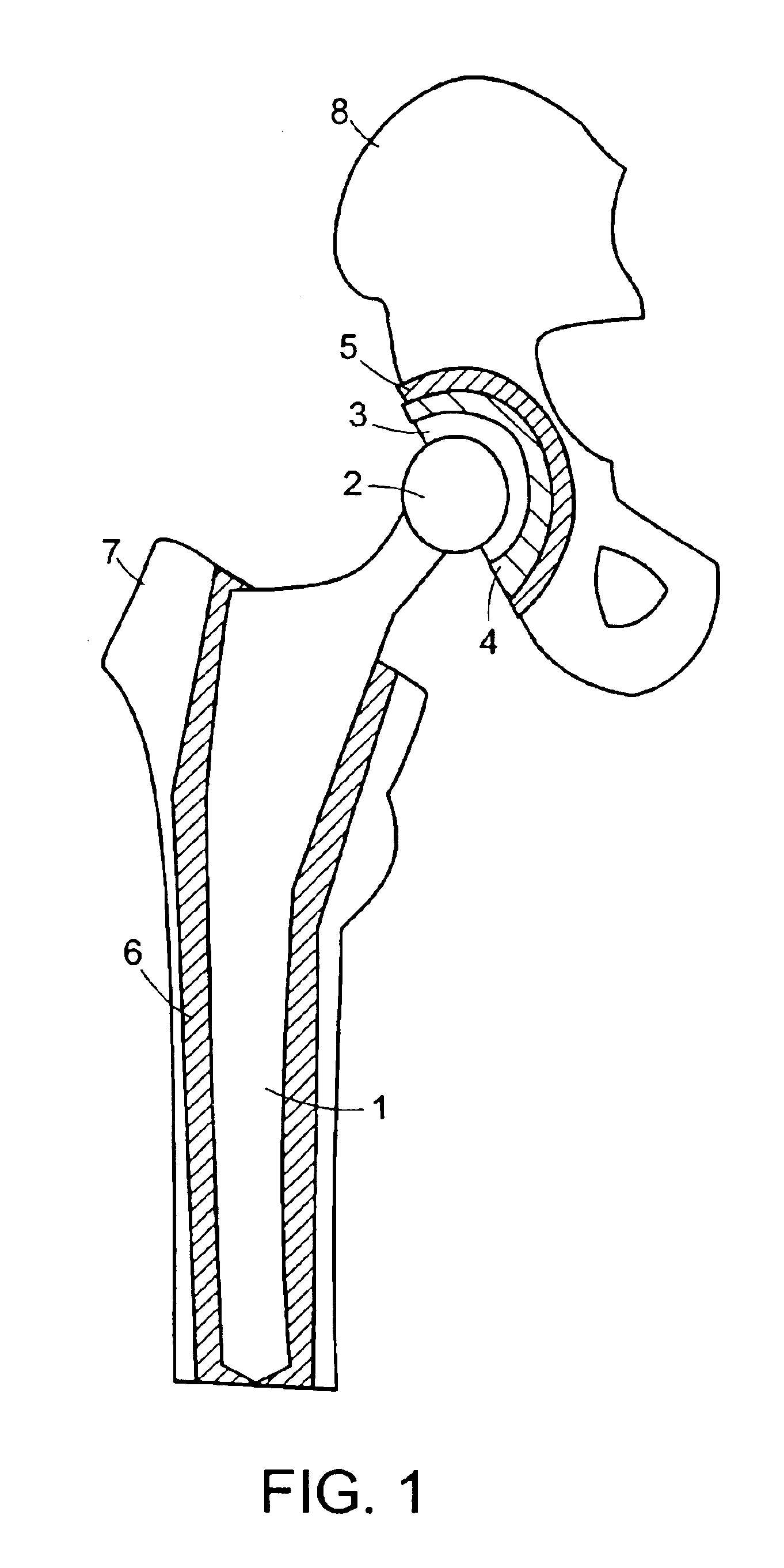
CROSS REFERENCES TO RELATED APPLICATIONS[0001]The present application is related to co-pending PCT Patent Applications being filed on even date, having Attorney Docket No.: 301788.3001-101 entitled System and Methods For Reducing Interfacial Porosity in Cements by Stephen H. Spiegelberg, Jeffrey W. Ruberti and Gavin J. C. Braithwaite and claims priority to U.S. Provisional Application No. 60 / 276,592 filed on Mar. 19, 2001.[0002]The entire contents of the above applications are incorporated herein by reference in entirety.BACKGROUND OF THE INVENTION[0003]There is an increase each year in the number of hip and knee total joint replacement surgeries, respectively total hip arthroplasties (THA) and total knee arthroplasties (TKA). Recently the number of surgeries exceeded 600,000 operations a year in the United States.[0004]The cost of an initial total hip replacement remains high. Revision surgeries to replace a failed hip prosthesis are typically more difficult and consequently more e...

Claims


Application Information

Patent Timeline
Patent Type & Authority Patents(United States)
IPC IPC(8): A61F2/30A61F2/46A61F2/00A61F2/32A61F2/38A61F2/36A61F2/34A61N7/00
CPCA61B17/8802A61F2/30771A61F2/4607A61F2002/30136A61F2002/30112A61F2002/30172A61F2002/30828A61F2002/30838A61F2002/30848A61F2002/30879A61F2002/30892A61F2002/3611A61F2002/3625A61F2002/4623A61F2002/4631A61F2002/4632A61F2002/4651A61F2002/4654A61F2002/4662A61F2002/4668A61F2002/4672A61F2002/4681A61F2002/469A61F2002/4697A61F2230/0004A61F2230/0017A61F2230/0052A61F2250/0023A61F2310/00011A61F2310/00952A61N7/00A61B2017/8844A61F2/30767A61F2/32A61F2/34A61F2/36A61F2/3662A61F2/389A61F2002/30011A61F2002/30041A61F2002/30138A61F2002/30845A61F2002/465A61F2002/4653A61F2002/4696A61F2/4603
Inventor SPIEGELBERG, STEPHEN H.RUBERTI, JEFFREY W.BRAITHWAITE, GAVIN G. C.
Owner CAMBRIDGE POLYMER GROUP
Why Eureka
Try Eureka