Switching circuit

a switching circuit and circuit technology, applied in the direction of dynamo-electric converter control, dc-ac conversion without reversal, electrical apparatus contruction details, etc., can solve the problems of compact circuit and lightness, reduce time and cost of circuit production, and prevent deformation of the bus bar itsel

Inactive Publication Date: 2005-04-26
TOYOTA JIDOSHA KK +1
View PDF14 Cites 14 Cited by
  • Summary
  • Abstract
  • Description
  • Claims
  • Application Information

AI Technical Summary

Benefits of technology

[0013]A switching circuit according to an embodiment of the invention includes a plurality of switching elements and a plurality of bus bars each serving as a conductor. The bus bars connect the switching elements to one of a power source and a load. Two or more of the plurality of bus bars are fixed to each other with an insulator interposed between adjacent ones of the two or more bus bars. The two or more of the plurality of bus bars with the insulator interposed therebetween are secured to a substrate of the switching circuit. As the aforementioned circuit requires no insert molding of the bus bars, the process for producing the switching circuit may be simplified, reducing the time and cost for producing the circuit. As the resin used for producing the circuit can be reduced, the resultant circuit may be compact and light. A plurality of bus bars are fixed with insulators interposed therebetween, thus preventing deformation of the bus bar itself. Furthermore, the combined bus bars and the insulators may serve as a reinforcing member of the substrate. Accordingly, the flexural rigidity and flexural strength of the switching circuit can be enhanced.
[0014]Two of the plurality of bus bars are fixed to each other with the insulator interposed therebetween. Current flows in one of the two bus bars in a direction opposite to a direction in which current flows in the other bus bar. In the switching circuit provided with the bus bars, an induced voltage (fly-back) generated during switching is increased by inductance distributed in the bus bars. This may prevent the switching circuit from conducting high-speed switching. According to the aforementioned aspect of the invention, however, the magnetic fields generated around the adjacent bus bars can be offset by current flowing along the bus bar in the opposite directions. The inductance of the bus bars, thus, can be reduced.

Problems solved by technology

As the resin used for producing the circuit can be reduced, the resultant circuit may be compact and light.

Method used


Image

  • Switching circuit
  • Switching circuit
  • Switching circuit

Examples


Embodiment Construction

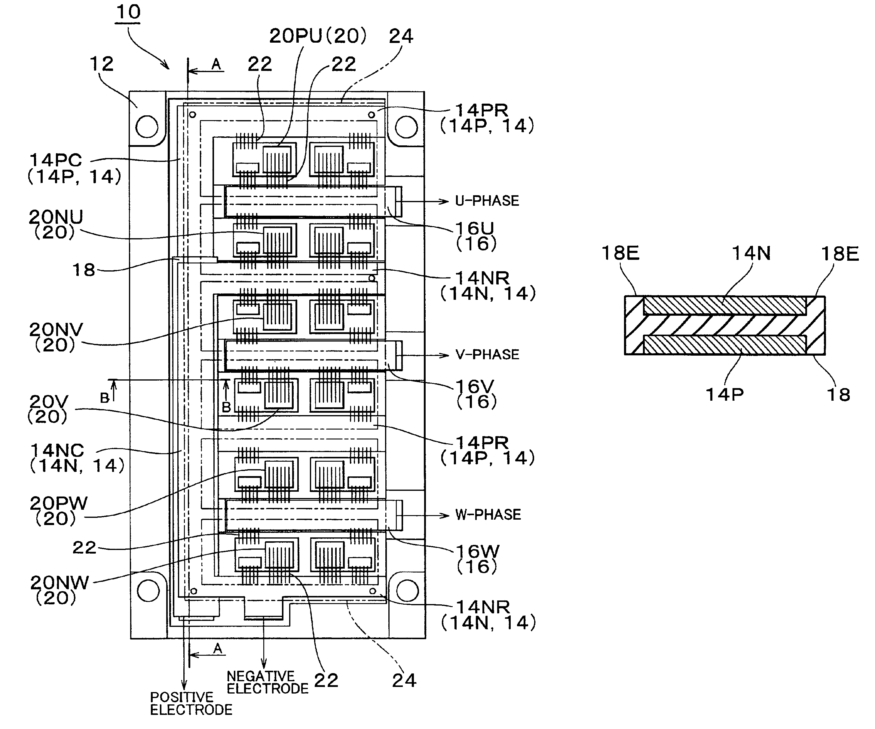
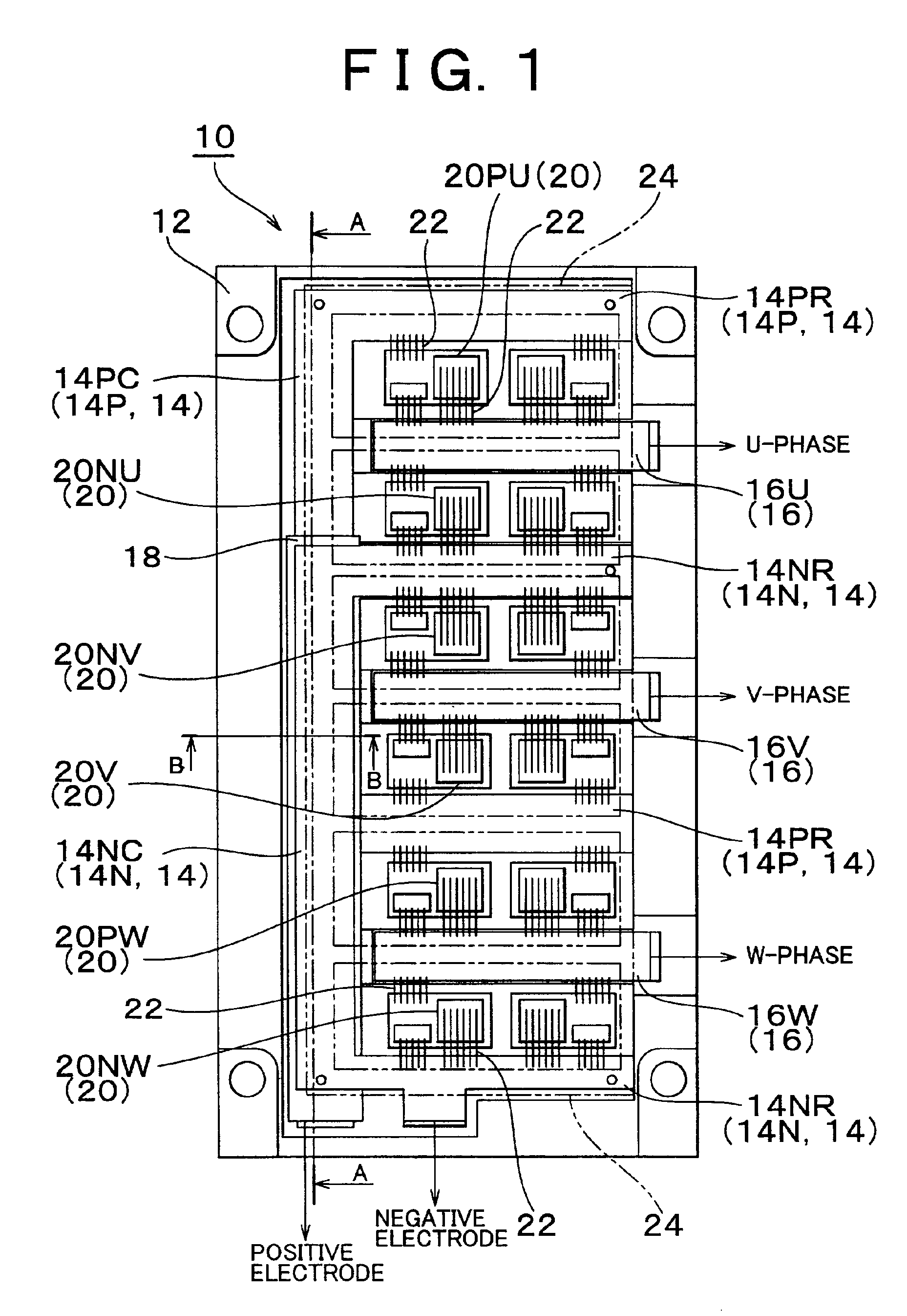
[0024]Embodiments of the invention will be described referring to the drawings. FIG. 1 is a plan view showing an essential portion of a switching circuit 10 of an embodiment of the invention. The direction of y-axis in figure such as FIG. 1 will be hereinafter called as a longitudinal direction, and the direction of x-axis in the figure will be hereinafter called as a lateral direction.

[0025]The switching circuit 10 serves to convert direct current into three-phase current (U-phase, V-phase, W-phase) as a circuit equivalent to an inverter as shown in FIG. 6. Referring to FIG. 1, the switching circuit 10 includes a plurality of bus bars 14 (14P, 14N) connected to a power source (not shown), and a plurality of bus bars (16U, 16V, 16W) connected to a load (not shown). The bus bar 14 includes longitudinal members 14PC, 14NC that extend in the longitudinal direction, and lateral members 14PR, 14NR that extend in the lateral direction. Each bus bar 16 is formed into a strip-like shape ext...


PUM


Abstract

In a switching circuit, at least two bus bars are fixed with an insulator interposed therebetween and secured to a substrate of the switching circuit. Being combined with the bus bars, the insulator serves not only to insulate those bus bars but also to enhance the bending rigidity and bending strength of the switching circuit. As current flows in one of the bus bars in a direction opposite to a direction in which current flows in the other bus bar, the inductance of the bus bars is reduced, resulting in the decreased fly-back voltage generated upon switching operation.

Description

INCORPORATION BY REFERENCE[0001]The disclosure of Japanese Patent Application No.2001-181345 filed on Jun. 15, 2001, including the specification, drawings and abstract are incorporated herein by reference in its entirety.BACKGROUND OF THE INVENTION[0002]1. Field of Invention[0003]The invention relates to a switching circuit provided with a plurality of bus bars serving as a conductor for coupling a switching element to a power source or a load.[0004]2. Description of Related Art[0005]Generally a metallic bus bar is well known as a conductor having a cross section area large enough to allow electric current to flow between circuit elements or between a circuit element and a power source or between a circuit element and a load in a power circuit such as a switching circuit for an inverter motor. FIG. 8 is a circuit diagram showing a generally employed switching circuit 40 serving as an inverter. FIG. 9 shows a plan view of the switching circuit 40.[0006]Referring to FIG. 8, the switch...

Claims


Application Information

Patent Timeline
Patent Type & Authority Patents(United States)
IPC IPC(8): H02M7/00H02G3/16H02M1/00H02M7/48H02P1/00
CPCH02M7/003H01L2224/49111H01L2224/49175H01L2924/19107H01L2924/13055H05K7/14329H01L2924/00H02P1/00H05K7/1432
Inventor NII, YOSHIBIDEHIRANO, NAOHIKO
Owner TOYOTA JIDOSHA KK
Why Eureka
Try Eureka