System and methods for driving an electro-optical device

a technology of electrooptical devices and driving methods, applied in the direction of static indicating devices, identification means, instruments, etc., can solve the problems of unobtainable desired display quality, and achieve the effect of good display quality display units

Inactive Publication Date: 2005-04-26
INTELLECTUAL KEYSTONE TECH LLC
View PDF4 Cites 59 Cited by
  • Summary
  • Abstract
  • Description
  • Claims
  • Application Information

AI Technical Summary

Benefits of technology

[0036]A second electronic apparatus according to the present invention can be characterized by having mounted t

Problems solved by technology

Especially when thin-film transistors are used as the driving transistors, a desired display quality m

Method used


Image

  • System and methods for driving an electro-optical device
  • System and methods for driving an electro-optical device
  • System and methods for driving an electro-optical device

Examples


Embodiment Construction

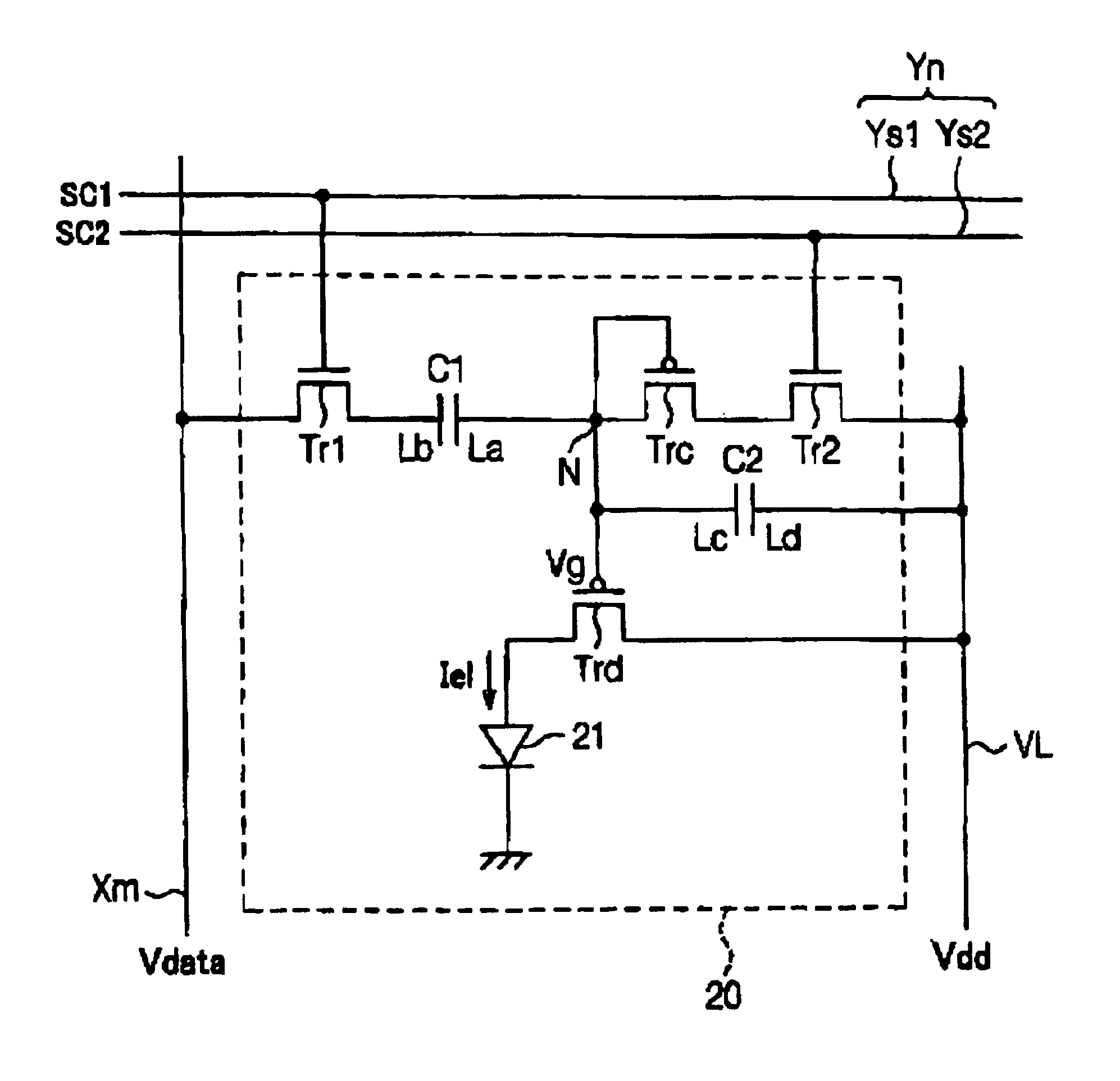
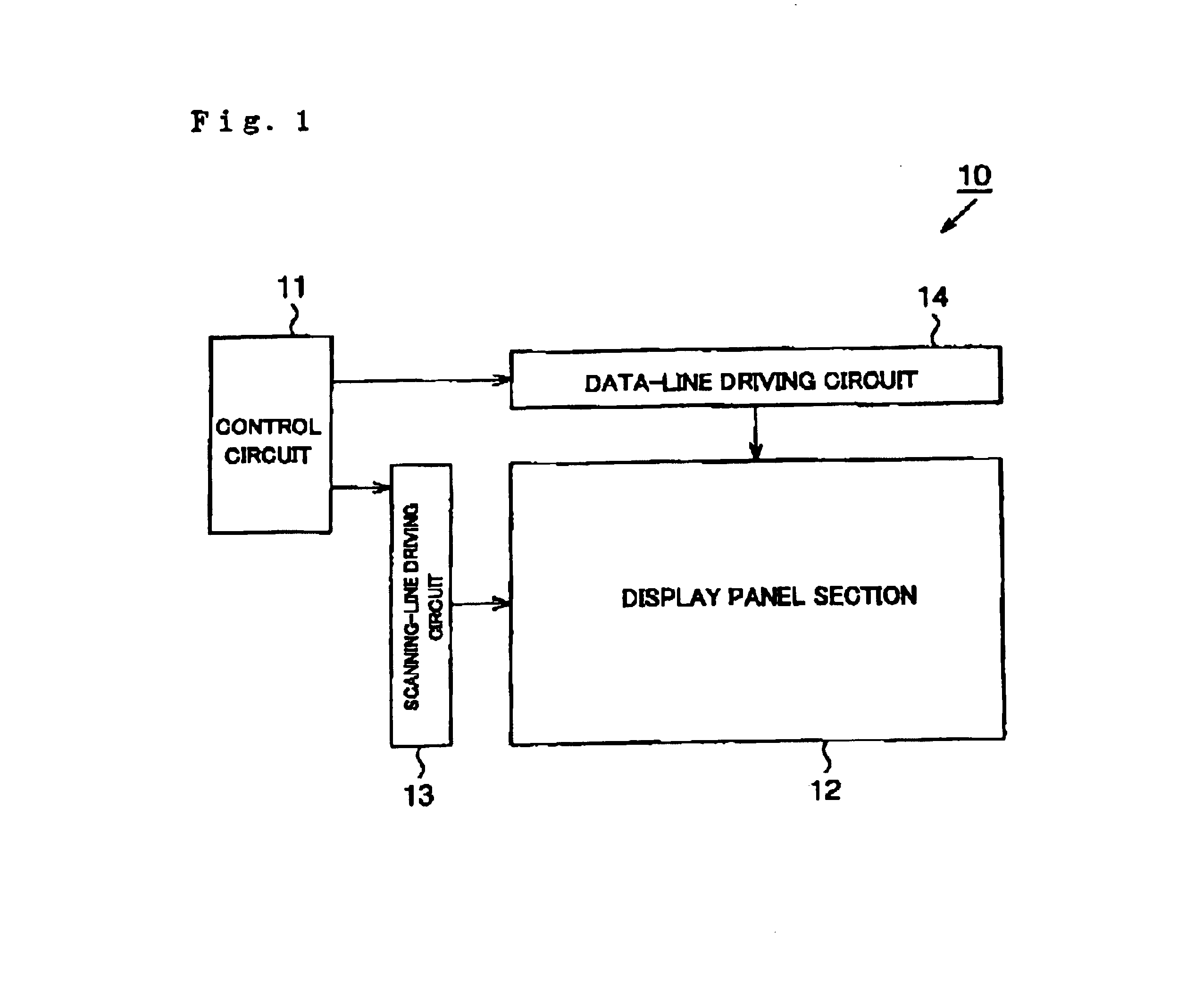
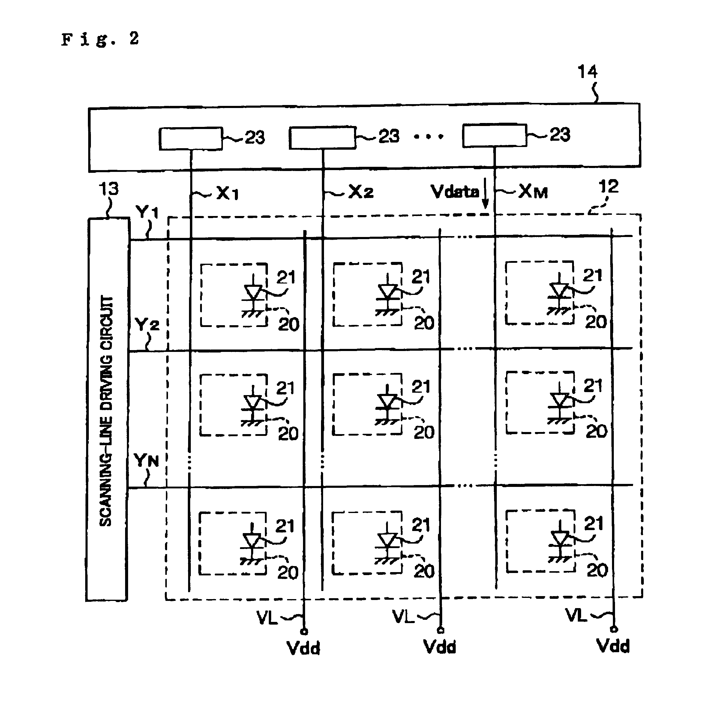
[0044]An organic EL display will be taken as an example of an electro-optical device according to an embodiment of the present invention and described by referring to FIG. 1 to FIG. 4. FIG. 1 shows the structure of the control block of the organic EL display. FIG. 2 is a block circuit diagram showing the internal circuit structure of a display panel section and a data-line driving circuit. FIG. 3 is a circuit diagram of a pixel circuit. FIG. 4 is a timing chart showing a driving method for the pixel circuit.

[0045]As shown in FIG. 1, the organic EL display 10 can include a control circuit 11, the display panel section 12, a scanning-line driving circuit 13, and the data-line driving circuit 14. The control circuit 11, the scanning-line driving circuit 13, and the data-line driving circuit 14 of the organic EL display 10 may be structured by independent electronic components. For example, each of the control circuit 11, the scanning-line driving circuit 13, and the data-line driving c...


PUM


Abstract

The invention provides an electronic circuit, a driving method for an electronic circuit, an electro-optical device, a driving method for an electro-optical device, and an electronic apparatus which can reduce the dispersion of the threshold voltages of transistors. A driving transistor, first and second switching transistors, an adjustment transistor, a coupling capacitor, and a holding capacitor form a pixel circuit. The threshold voltage of the adjustment transistor is applied to the gate of the driving transistor. According to the present invention, the luminance gradation of a display element, such as an organic EL element, can be precisely controlled according to a data voltage.

Description

BACKGROUND OF THE INVENTION[0001]1. Field of Invention[0002]The present invention relates to electronic circuits, driving methods for electronic circuits, electro-optical devices, driving methods for electro-optical devices, and electronic apparatus.[0003]2. Description of Related Art[0004]An active-matrix driving method is one of driving methods for electro-optical devices having electro-optical elements, such as liquid-crystal elements, organic EL elements, electro-phoresis elements, and electron-emission elements. In electro-optical devices which use the active-matrix driving method, a plurality of pixel circuits are disposed in a matrix manner in a display panel section. Each of the plurality of pixel circuits can include an electro-optical element and a driving transistor for supplying driving power to the electro-optical element.[0005]Among those elements, since current-driven elements, as described in International Publication No. WO98 / 36407, driven by current, such as organi...

Claims


Application Information

Patent Timeline
IPC IPC(8): G02F1/133G02F1/13G09G3/30G09F9/30G09G3/00G09G3/20H01L29/04H01L29/02H01L29/66H01L29/786H01L31/036H01L29/80H05B33/14H01L51/50G09G3/32H01L27/12H01L27/32H01L29/10H01L31/0376H01L31/20
CPCG09G3/3233H01L27/12G09G2300/0819G09G2300/0852G09G2310/0262G09G2320/043G09G2310/0251G09G3/30
Inventor MIYAZAWA, TAKASHI
Owner INTELLECTUAL KEYSTONE TECH LLC
Why Eureka
Try Eureka