Dynamic, digitally controlled, temperature compensated voltage reference

a voltage reference and temperature compensation technology, applied in the direction of electric variable regulation, process and machine control, instruments, etc., can solve the problems of reference voltage drift, insufficient control of voltage reference, and large influence on the stability of such current sources

Active Publication Date: 2005-04-26
MICROCHIP TECH INC
View PDF7 Cites 40 Cited by
  • Summary
  • Abstract
  • Description
  • Claims
  • Application Information

AI Technical Summary

Benefits of technology

[0010]Thus, various embodiments of the invention may provide a means for dynamically, digitally controlling a voltage reference by way of employing a completely digital function to control the gain of a voltage reference amplifier whose input may be a band gap derived voltage reference, and whose output may be a derived voltage reference corresponding to the controlled input voltage reference. Inputs to the digital function may include a programmable trim value and a substrate temperature value provided by a temperature monitor.

Problems solved by technology

Because field effect transistors are commonly used to implement current sources, the stability of such current sources is greatly affected by the stability and accuracy of the reference voltage applied to the gate of the field effect transistor (FET).
This method, however, may not provide sufficient control over the voltage reference since it is used during characterization and probe, not during normal circuit operations.
For example, temperature variations in the die may cause a reference voltage drift during normal operations.
Since the fuses are cut during characterization and probe, they would provide no means of controlling such a drift.
While it is possible to control the drift during normal circuit operations using complex analog circuits, such methods are in many cases impractical and limited by die size and other factors.

Method used


Image

  • Dynamic, digitally controlled, temperature compensated voltage reference
  • Dynamic, digitally controlled, temperature compensated voltage reference
  • Dynamic, digitally controlled, temperature compensated voltage reference

Examples


Embodiment Construction

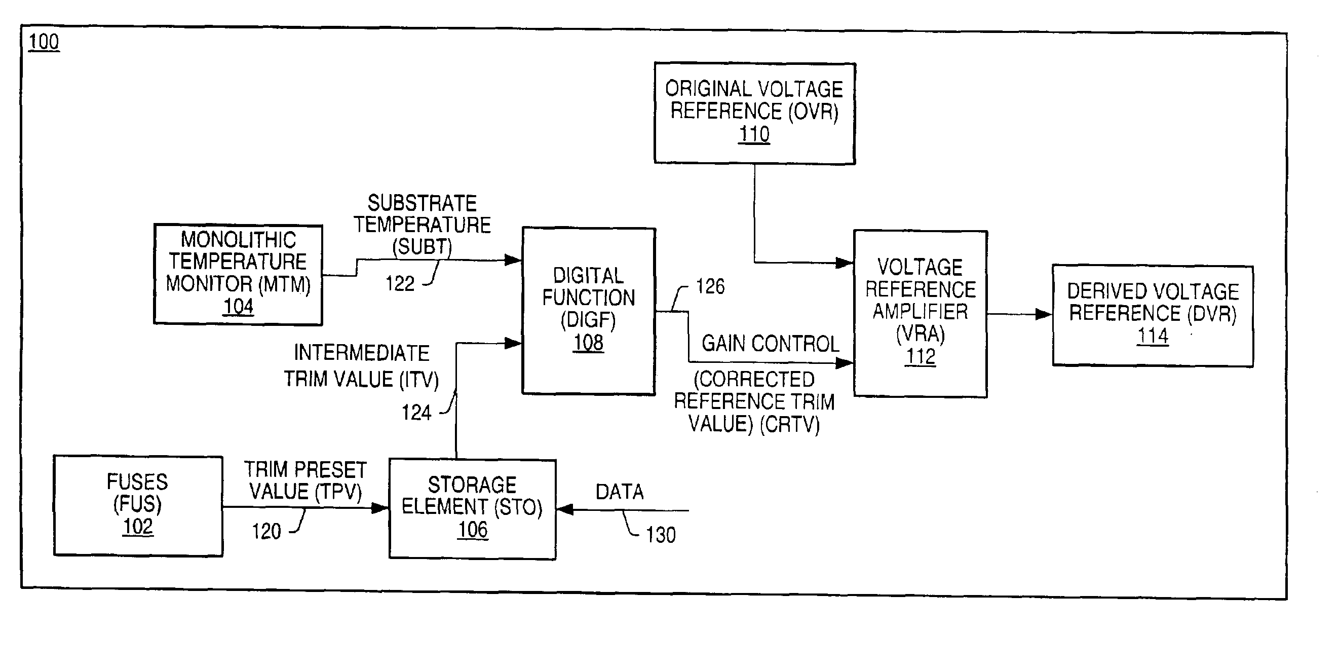
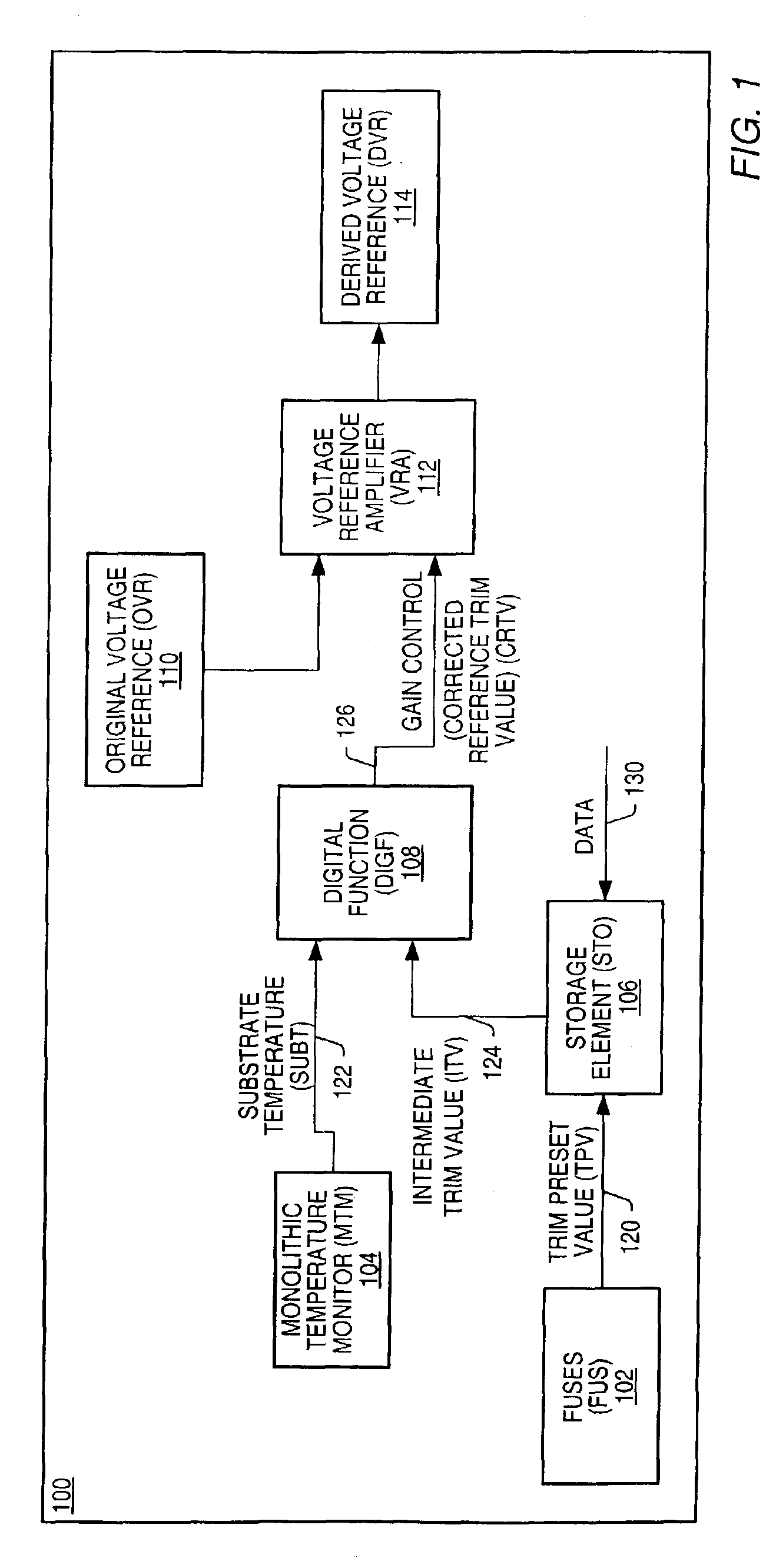
[0018]FIG. 1 illustrates the block diagram of a voltage reference system 100 implemented in accordance with one set of embodiments of the present invention. In one embodiment, the system comprises a voltage reference amplifier (VRA) 112, a storage element (STO) 106, a set of fuses (FUS) 102, a digital function (DIGF) 108, and a monolithic temperature monitor (MTM) 104. The set of fuses may comprise any number of fuses. The fuses may be used to control the value of a trim preset value (TPV) 120, which may be used by STO 106 as an input preset value. Data 130 may also be stored in STO 106, resulting in STO 106 providing an intermediate trim value (ITV) 124 as an input to DIGF 108. In one embodiment, an output of MTM 104 is also coupled to DIGF 108, supplying a measured substrate temperature value (SUBT) 122 as an input to DIGF 108. Corrected reference trim value (CRTV) 126 is an output of DIGF 108 and is used to control a gain of VRA 112. In one embodiment the input of VRA 112 is an o...


PUM


Abstract

A voltage reference is dynamically and digitally controlled by a digital function. The digital function may be implemented as a digital calculation or look up table. Inputs to the function include a modifiable trim value stored in a trim register, and a substrate temperature value. The preset value of the trim register is a trim preset value generated by cutting fuses and/or leaving fuses uncut. The cutting may be performed using laser trimming-devices. The output of the digital function is a corrected reference trim value that controls the gain of a voltage reference amplifier whose input is a band gap based voltage reference, and whose output is a derived voltage reference. The substrate temperature value is provided by a monolithic temperature monitor whose sensor may be on the same die as the derived voltage reference. The derived voltage reference provides a stable reference voltage that is dynamically and digitally controllable, to a host system that requires a voltage reference.

Description

BACKGROUND OF THE INVENTION[0001]1. Field of the Invention[0002]This invention relates generally to the field of analog integrated circuit design and, more particularly, to voltage reference design.[0003]2. Description of the Related Art[0004]In the design of most analog integrated circuits, more specifically when using complementary metal-oxide-semiconductor (CMOS) technology, a stable reference voltage is often required to insure proper circuit operation. Functional circuit elements of these integrated circuits often employ current sources that are expected to provide stable currents. Such circuit elements can be current mirrors, differential amplifiers or operational amplifiers. Because field effect transistors are commonly used to implement current sources, the stability of such current sources is greatly affected by the stability and accuracy of the reference voltage applied to the gate of the field effect transistor (FET).[0005]An example of an integrated circuit function that...

Claims


Application Information

Patent Timeline
Patent Type & Authority Patents(United States)
IPC IPC(8): G06F15/16G06F15/177G06F17/50G06F19/00G06F9/00H03F3/45G06F1/26
CPCG06F1/26
Inventor BURSTEIN, STEVENBEKKER, LENPOPPER, JAY D.
Owner MICROCHIP TECH INC
Why Eureka
Try Eureka