System and method for detecting and classifying biological particles

a biological particle and biological particle technology, applied in the field of instruments and methods for analyzing airborne biological particles, can solve the problems of increasing the probability of not detecting a certain percentage of biological particles at elevated aerosol concentrations, causing death, and causing death, and causing death

Inactive Publication Date: 2005-04-26
UNKNOWN +1
View PDF19 Cites 97 Cited by
  • Summary
  • Abstract
  • Description
  • Claims
  • Application Information

AI Technical Summary

Benefits of technology

[0020]When a biological particle is illuminated with a laser diode having a wavelength that can be absorbed by the particle's endogenous fluorophores, the absorbing endogenous fluorophores fluoresce. The present invention detects the light emitted from the fluorescing biological particles. Preferably, this is done by placing short or long bandpass filters in front of an array of photo-multiplier tubes (PMT) to admit only selected frequencies of light to be received by each PMT in the array. The use of filters allows the present invention to detect multiple fluorescing frequencies in separate channels.

Problems solved by technology

Some of these airborne particles can be dangerous, and even life threatening.
Aerosol attacks delivering, as low as, a biological particle per liter of air can still provide a life threatening level of biological warfare agents.
Consequently (referring to Table 1), a major challenge for real-time detection systems is that they be capable of detecting trace levels of airborne biological agents.
One problem potentially encountered with such triggered systems is an increased likelihood of not detecting a certain percentage of biological particles at elevated aerosol concentrations due to triggering limitations.
This is a significant issue when detecting airborne biological particles due to the fact that the percentage of biological particles in most environments is less than 0.1% of the total aerosol content.

Method used


Image

  • System and method for detecting and classifying biological particles
  • System and method for detecting and classifying biological particles
  • System and method for detecting and classifying biological particles

Examples


Embodiment Construction

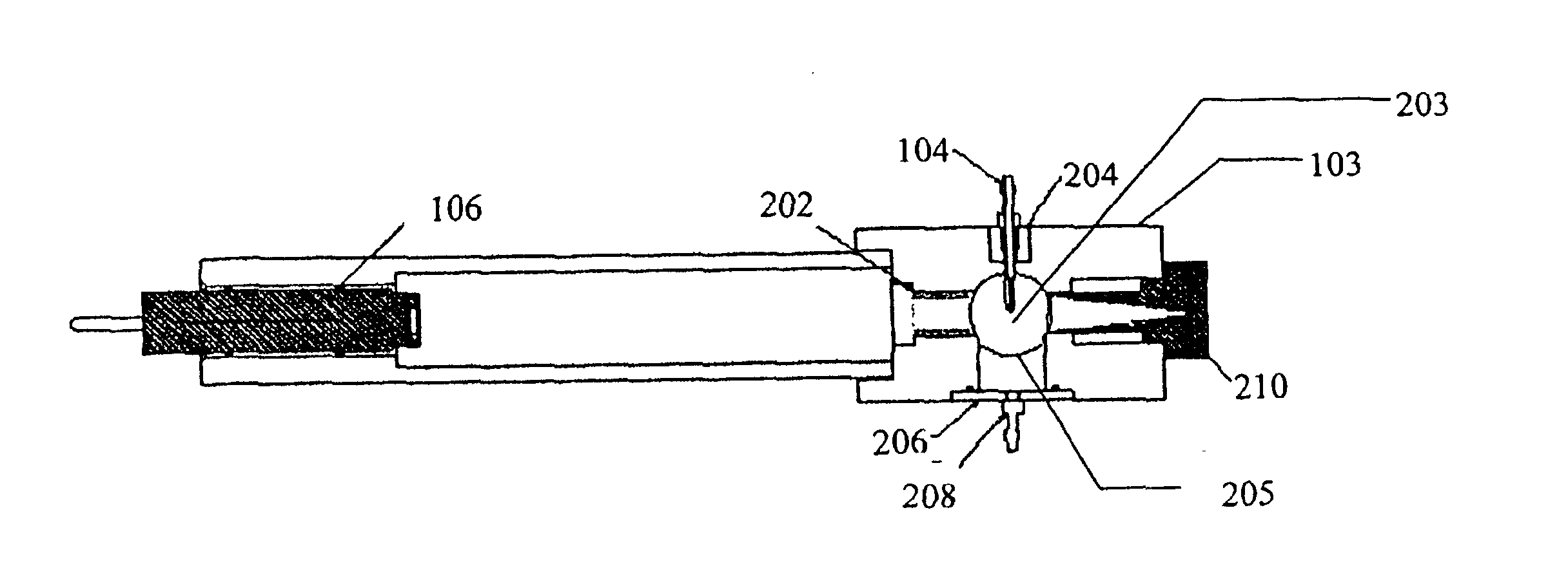
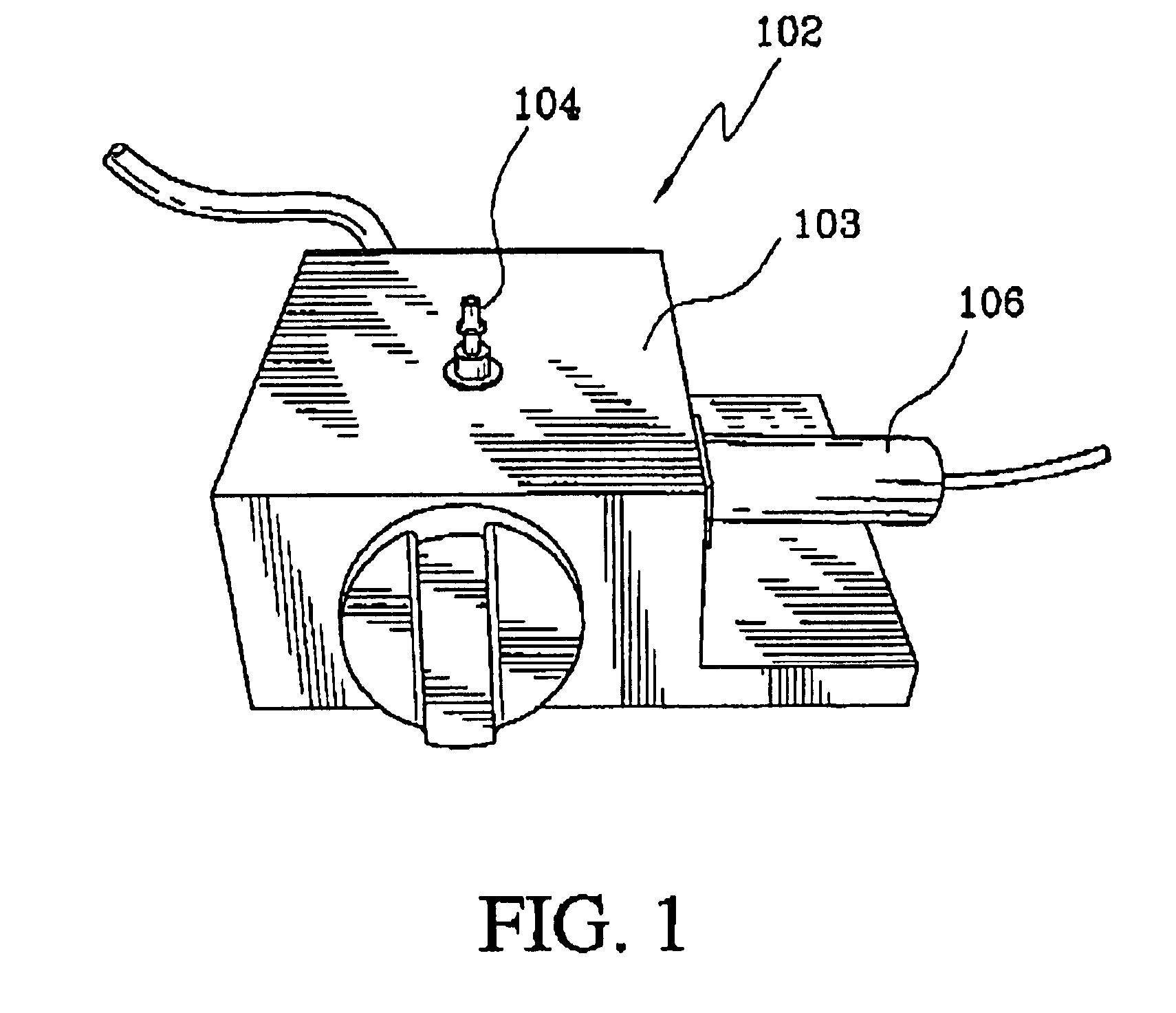
[0043]The present invention provides real-time detection of the presence of biological particles that are sampled from the air in a real-time manner. Preferably, the detection process of the present invention comprises two primary components. The first component includes collecting the aerosol containing airborne particles, introducing the collected aerosol into a laser's viewing region and collecting the amount of generated light. The second component of the detection process includes analysis of the signals collected from a sensor.

[0044]The sensor comprises four primary components. An aerosol inlet probe is used to analytically introduce the aerosol to a laser's viewing volume. An aerosol outlet probe is preferably configured to remove the aerosol that exits from the laser's view volume to minimize fouling of the optic region of the sensor itself. An illumination source that comprises either a continuous wave laser or a modulated laser with a repetition frequency that exceeds 50 M...


PUM

PropertyMeasurementUnit
repetition frequencyaaaaaaaaaa
wavelengthaaaaaaaaaa
fluorescing wavelengthaaaaaaaaaa

Abstract

A continuous wave laser excites a biological particle. Detection channels are created to detect light scattered by the biological particle, and to detect any auto-fluorescence emitted by the biological particle. Additional channels can also detect light emitted by auto-fluorescence of the biological particle when simultaneously excited by light at harmonics of the laser's fundamental wavelength. The biological particle is identified using Mie scattering and auto-fluorescence. Ratio-metric calculations generated by calculating ratios of detected peak heights or integrated pulse values in the channels provides additional information for identifying and classifying the biological particle. A warning or alert can be provided if the identified biological particle is a particle of interest.

Description

[0001]This application claims the benefit of U.S. Provisional Application No. 60 / 331,048, filed Nov. 7, 2001, and U.S. Provisional Application No. 60 / 383,776, filed May 30, 2002, both of which are herein incorporated by reference in their entireties.BACKGROUND[0002]1. Field of the Invention[0003]The present invention relates generally to instruments and methods for analyzing airborne biological particles. More particularly, the present invention relates to instruments and methods for classifying and identifying airborne biological particles in real-time based on both their size and laser-induced auto-fluorescence of their biological components.[0004]2. Background of the Invention[0005]Numerous airborne pathogens and allergens can be found in or introduced into an environment. These airborne particles can be naturally occurring or artificially produced. Some of these airborne particles can be dangerous, and even life threatening. For example, such airborne particles can include biolo...

Claims


Application Information

Patent Timeline
Patent Type & Authority Patents(United States)
IPC IPC(8): G01N21/64G01N21/47G01N21/85
CPCG01N15/0205G01N21/47G01N21/6402G01N21/6486G01N21/645G01N2021/6421G01N21/85
Inventor SILCOTT, DAVID B.TILLEY, GREG A.WHITMAN, BRIAN R.PRATT, STEVEN J.
Owner UNKNOWN
Why Eureka
Try Eureka