Optical signal receiver and method with decision threshold adjustment based on a total percentage error indicator field of the invention

a technology of optical communication network and decision threshold adjustment, which is applied in the direction of transmission monitoring, instruments, coding, etc., can solve the problems of signal degradation, ber degradation in the absence of re-optimized decision, and signals transported over optical communication network degradation. to achieve the effect of reducing the ber

Inactive Publication Date: 2005-04-26
CIENA
View PDF7 Cites 32 Cited by
  • Summary
  • Abstract
  • Description
  • Claims
  • Application Information

AI Technical Summary

Benefits of technology

[0011]The present invention is organized about the concept of providing an optical receiver configuration and a method of controlling an optical signal receiver that adjusts a decision threshold that reduces the BER.

Problems solved by technology

It is well known that signals transported over optical communication networks suffer degradation between associated transmitters and receivers.
Signal degradation may result from a variety of system parameters including the total transmission distance, the transmission fiber type, the number of optical amplifications to a signal, the number of system channels, etc.
A difficulty with such receiver designs, however, is that the eye diagram itself depends on all of the above-mentioned parameters that effect signal quality.
Such changes can alter the received “eye diagram” such as in the eye diagram shown in FIG. 1b, leading to a degradation of the BER in the absence of a re-optimized decision threshold.

Method used


Image

  • Optical signal receiver and method with decision threshold adjustment based on a total percentage error indicator field of the invention
  • Optical signal receiver and method with decision threshold adjustment based on a total percentage error indicator field of the invention
  • Optical signal receiver and method with decision threshold adjustment based on a total percentage error indicator field of the invention

Examples


Embodiment Construction

[0037]The following detailed description of the invention refers to the accompanying drawings. The same reference numbers in different drawings identify the same or similar elements. Also, the following detailed description does not limit the invention. Instead, the scope of the invention is defined by the appended claims and equivalents thereof.

[0038]The expression “optically communicates” as used herein refers to any connection, coupling, link or the like by which optical signals carried by one optical system element are imparted to the “communicating” element. Such “optically communicating” devices are not necessarily directly connected to one another and may be separated by intermediate optical components or devices. Likewise, the expressions “coupled”, “connection” and “operative connection” as used herein are relative terms and do not require a direct physical connection.

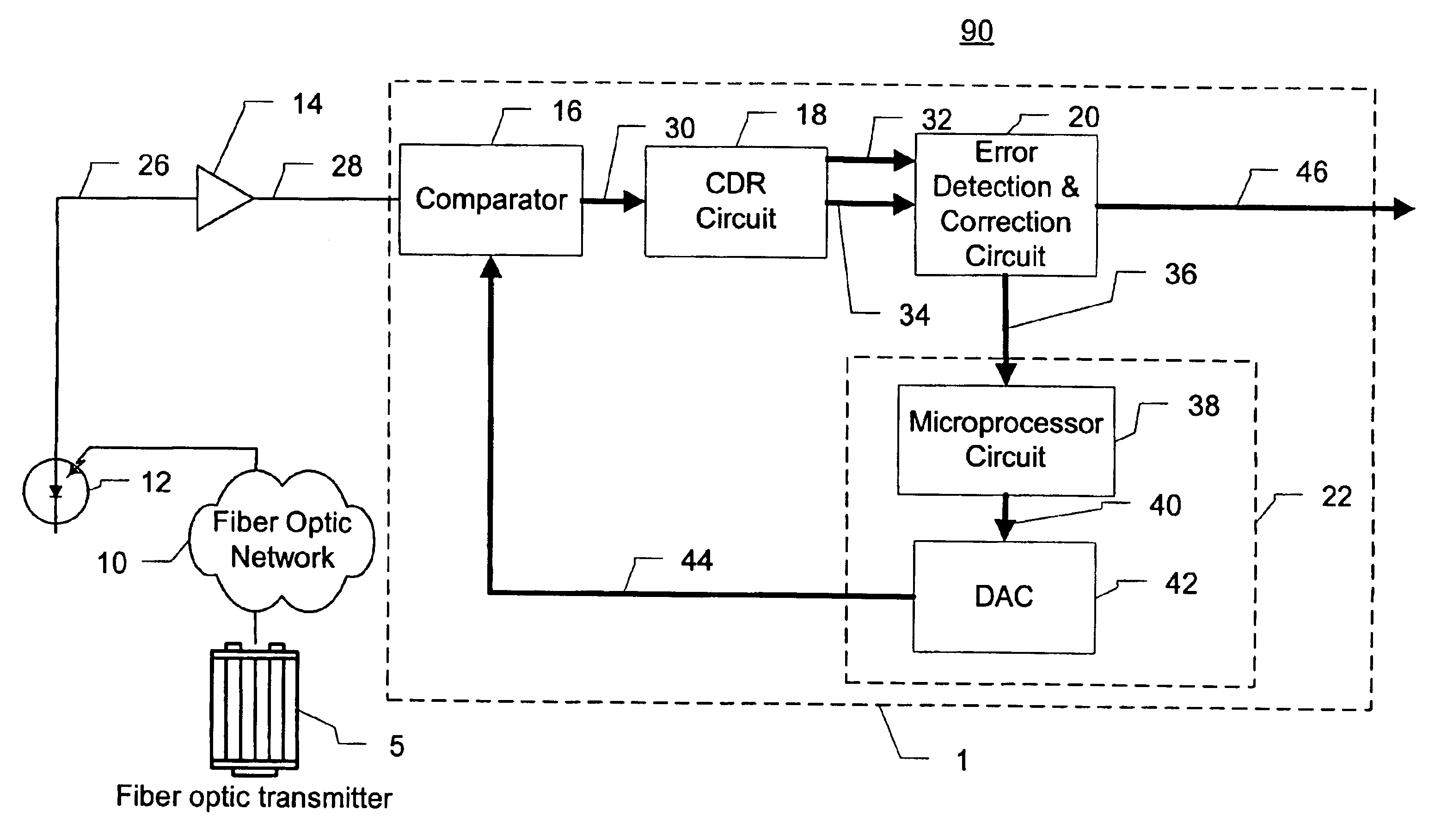
[0039]FIG. 2 illustrates an exemplary embodiment of a receiver circuit 1 consistent with the invention. The...


PUM


Abstract

An optical receiver configuration and method of controlling an optical signal receiver adjusts a decision threshold to reduce the bit error rate (BER). The receiver includes a comparator having a data input and a digital data output. An error detection & correction circuit provides an error signal representative of the number of corrected “1”s and “0”s in the data output from the comparator. Based on the error signal, a control circuit modifies the comparator decision threshold in a direction to reduce the BER of the receiver. Dynamic modification of the decision threshold may also be accomplished. A total percentage error indicator is preferably used as the basis of changing the decision threshold value. The total percentage error indicator may be used to variably adjust the decision threshold by an amount that varies according to the magnitude of the total percentage error indicator to thereby more quickly arrive at an acceptable decision threshold and prevent overshoot. A searching method may also be used to determine the usable range of the comparator before tuning the decision threshold.

Description

[0001]The present invention relates in general to receivers and methods of receiving for communication systems and, in particular, to an optical signal receiver and optical signal receiving method including decision threshold adjustment.BACKGROUND OF THE INVENTION[0002]It is well known that signals transported over optical communication networks suffer degradation between associated transmitters and receivers. Signal degradation may result from a variety of system parameters including the total transmission distance, the transmission fiber type, the number of optical amplifications to a signal, the number of system channels, etc.[0003]Optical networks are, however, being developed with ever-increasing signal transmission speeds and distances. Channel counts have also been increasing in wavelength division multiplexed transmission systems. The greater transmission distances, speeds and higher channel counts directly effect received signal quality.[0004]To maintain high fidelity signa...

Claims


Application Information

Patent Timeline
Patent Type & Authority Patents(United States)
IPC IPC(8): H04B10/152H04B10/158H04B10/08H04B10/02
CPCH04B10/07953H04L25/063H04B10/695H04B10/0799
Inventor CORNELIUS, STEVE W.
Owner CIENA
Why Eureka
Try Eureka