Wire saw with means for producing a relative reciprocating motion between the workpiece to be sawn and the wire

a technology of relative reciprocating motion and wire saw, which is applied in the direction of metal sawing apparatus, sawing apparatus, stone-like material working apparatus, etc., can solve the problems of producing other irregularities, unable to avoid undulation, and the oscillation position does not permit undulation, so as to achieve reliable construction and high quality of sawed products.

Inactive Publication Date: 2005-05-03
APPLIED MATERIALS SWITZERLAND
View PDF8 Cites 21 Cited by
  • Summary
  • Abstract
  • Description
  • Claims
  • Application Information

AI Technical Summary

Benefits of technology

[0007]Thus the relative positions of the wire layer and the axis of oscillation can be adjusted and varied according to applications. The precision of the slices and sawed pieces is thus greatly improved. The surface condition of the obtained slices is very regular, given that a movement of oscillation with a precisely positioned axis permits obtaining a polishing and lapping effect during sawing. All undulation and roughness can be avoided by superposition in the course of sawing of a lapping and rectification operation arising from oscillations of the piece to be sawed about an axis whose position can be adjusted and programmed in an optimal manner. Moreover, this particular oscillation permits better control of the penetration of the abrasive along the sawing path and clearing effect of the wire thereby improving its sawing efficiency.

Problems solved by technology

Thus this fixed position of oscillation does not permit avoiding undulations and striations in the obtained slices.
Moreover, it can even produce other irregularities during cutting due to an oscillation with inadequate positioning.

Method used


Image

  • Wire saw with means for producing a relative reciprocating motion between the workpiece to be sawn and the wire
  • Wire saw with means for producing a relative reciprocating motion between the workpiece to be sawn and the wire
  • Wire saw with means for producing a relative reciprocating motion between the workpiece to be sawn and the wire

Examples


first embodiment

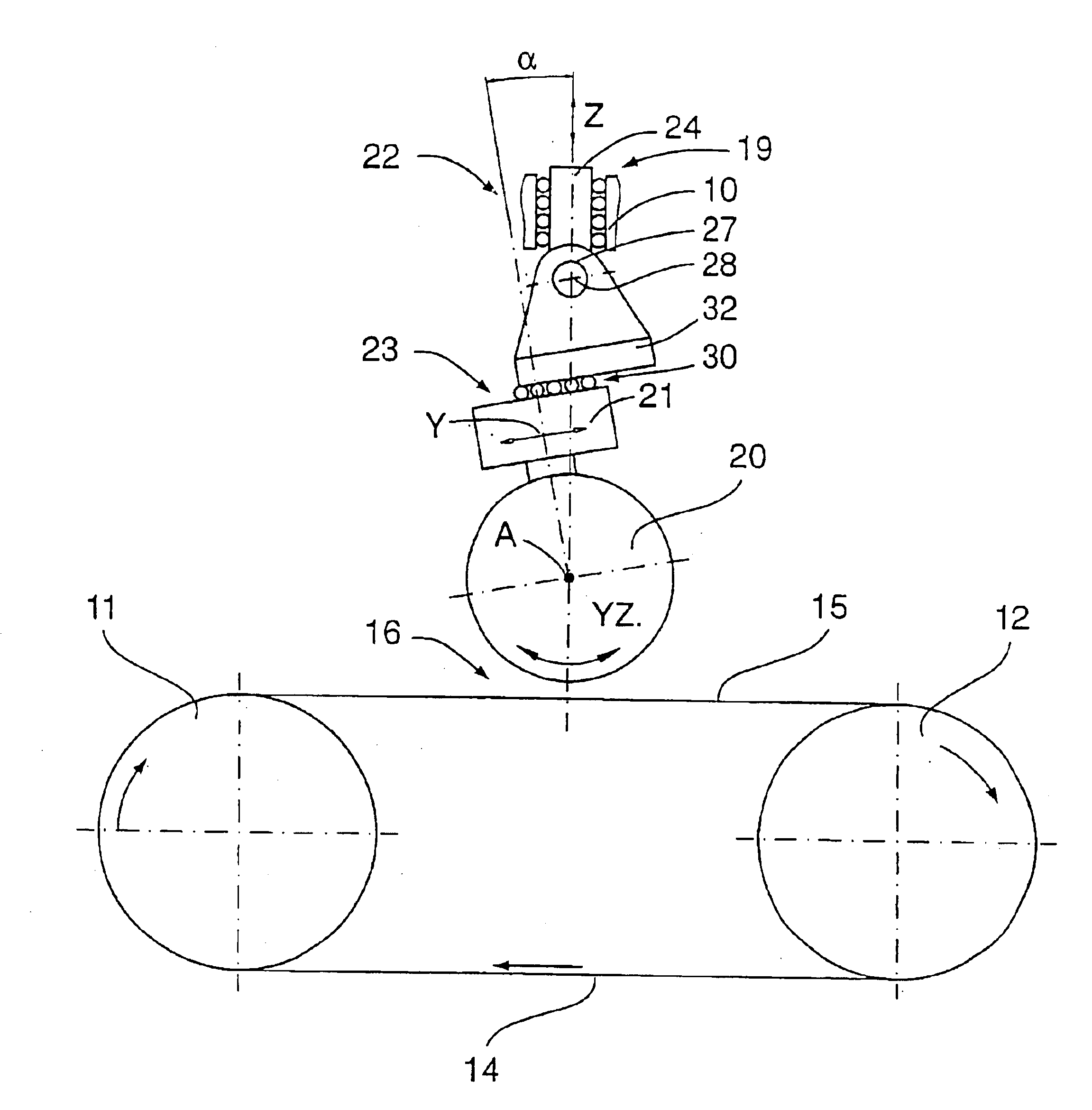
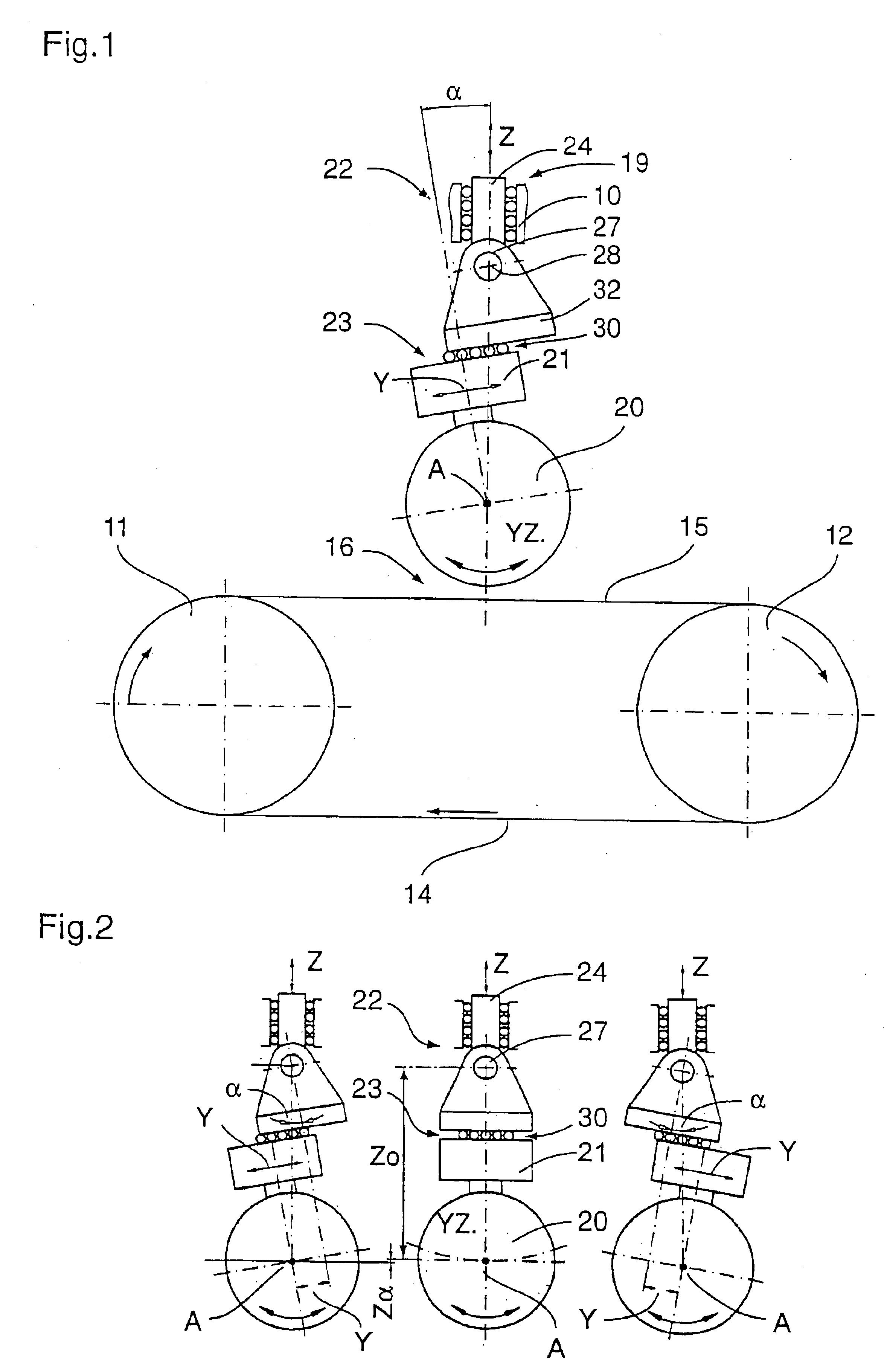
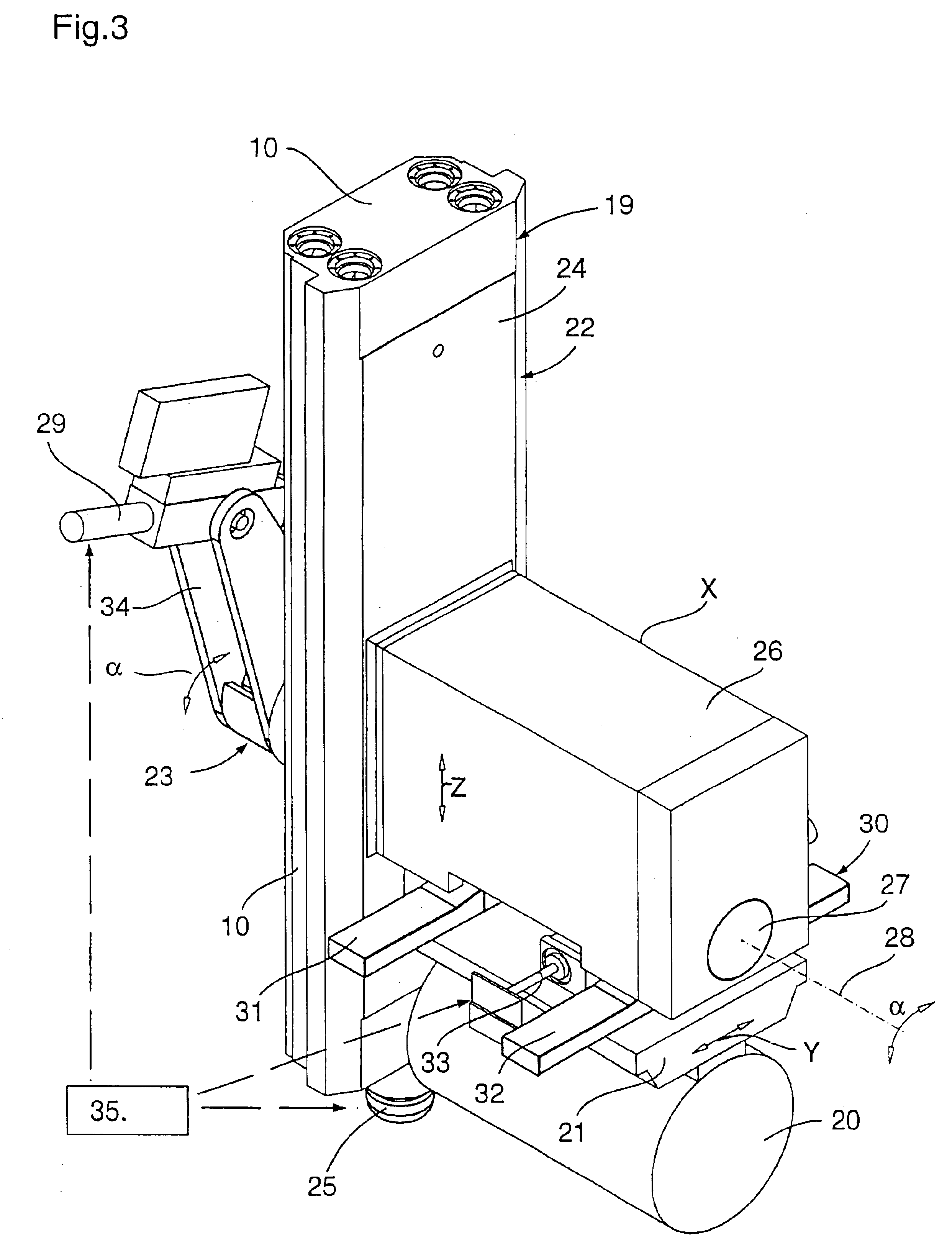
[0028]The wire sawing device or machine shown in FIGS. 1 to 3 constitutes a This device comprises a frame 10 supporting at least two wire guide cylinders 11, 12 on which a wire is wound spirally to form at least one layer of wires 15 whose distance between two adjacent wires fixes the thickness of the sawed slices. The wire guide cylinders 11, 12 are for this purpose generally clad with a layer of synthetic material engraved with throats defining the interval between adjacent wires of the layer. The wire is either covered with a fixed abrasive or supplied continuously with a loose abrasive, generally in suspension in a liquid. The wire thus serves to carry the abrasive particles which themselves perform the sawing work in a so-called sawing zone 16. This wire is desirably constituted of spring steel with a diameter comprised between 0.1 and 0.2 mm so as to saw the blocks of hard material or of more particular composition such as silicon, ceramic, compounds of elements of groups III...

second embodiment

[0041]The second embodiment shown in FIGS. 5 and 6 has a different mechanical construction of the control device 52 for the movements of the piece 20 to be sawed and of the oscillation device 53. This latter also comprises a slide 54 mounted movably on the frame 10 in a direction Z and driven by a motor 55. A table 56 with transverse movement is mounted on the slide 54 and can be moved by means of α motor 57 in a Y direction perpendicular to the cutting direction Z and parallel to the wires of the layer of wires. This table 56 carries a rotatable plate mechanism 58 driven by a motor 59 to carry out an angular movement a about an axis 60 of rotation parallel to a direction X and perpendicular to the directions Y and Z.

[0042]The rotatable plate 58 is secured to the support table 61 on which is fixed the piece 20 to be sawed. The motors 55, 57 and 59 are controlled by a control unit. The oscillatory movement of the piece to be sawed is also obtained by two translatory movements in dire...

third embodiment

[0047]In the third embodiment shown in FIG. 7, the oscillation device 73, instead of providing two translations and one rotation, has two effective axes 74, 75 of rotation and translation in the cutting direction Z. Thus, the piece 20 to be sawed is mounted on a support table 21 which is secured to a first oscillating member or lever 76 pivotally mounted about a first axis 74 of rotation on a second oscillating member or lever 77 mounted pivotably about a second axis 75 of rotation on a slide 78 arranged movably in the cutting direction Z on the stationary frame 10. Thanks to the slide 78 and its two oscillating arms 76, 77 which can be driven by motors (not shown) controlled by a control unit, it is possible to produce an oscillatory movement of the piece about an oscillation axis A whose spatial position can be adjusted and programmed such that this oscillation axis A is located at any time at a programmable and adjustable distance from the second axis 75 of rotation or from a ref...


PUM

PropertyMeasurementUnit
thicknessaaaaaaaaaa
diameteraaaaaaaaaa
diameteraaaaaaaaaa

Abstract

A sawing device includes a wire assembly (15) supported on wire-guiding rolls (11, 12) and pressed against a workpiece to be sawn (20) fixed on a support table (21). An oscillating device (23) produces a relative reciprocating movement between the workpiece and the wire assembly (15) around an oscillation axis (A) whereof the spatial position can be adjusted and programmed so that the oscillation axis (A) is at a programmable and adjustable distance from an effective axis of rotation (28) of the oscillating device (23).

Description

BACKGROUND OF THE INVENTION[0001]The present invention relates to a wire sawing device comprising at least one layer of wires adapted to move with alternate or continuous movement, this layer of wires being pressed against a piece to be sawed and supported by wire guide cylinders, first means being provided to carry out a relative advancing movement between the piece to be sawed and the layer of wires in a cutting direction contained in a cutting plane, second means being provided to carry out a relative oscillating movement between the piece to be sawed and the layer of filaments about an axis of oscillation perpendicular to the cutting plane.[0002]In this type of device, the filament is wound spirally about wire guide cylinders and forms between two wire guide cylinders at least one layer of parallel wires whose distance between successive wires fixes the thickness of the slices. Moreover, the plane of the layer or layers of wires forms, in known devices, a fixed angle generally p...

Claims


Application Information

Patent Timeline
Patent Type & Authority Patents(United States)
IPC IPC(8): B23D57/00B28D7/00B28D5/00B24B27/06
CPCB23D57/0046B28D7/005B28D5/0082B23D57/0061Y10T83/9292Y10T83/8798Y10T83/869
Inventor HAUSER, CHARLES
Owner APPLIED MATERIALS SWITZERLAND
Why Eureka
Try Eureka