
Igniter with a push-button and an elastic bar

a push-button and elastic bar technology, applied in the field of ignitor, can solve the problems of imperfect security and no function of the locking switch, and achieve the effect of easy firing

Inactive Publication Date: 2005-05-03
JUDENG ZHANG
View PDF34 Cites 28 Cited by
  • Summary
  • Abstract
  • Description
  • Claims
  • Application Information

AI Technical Summary

Benefits of technology

[0004]The object of this invention is to provide igniter with a safety unit which can solve the problem mentioned above and can't be fired easily by children by misplay.
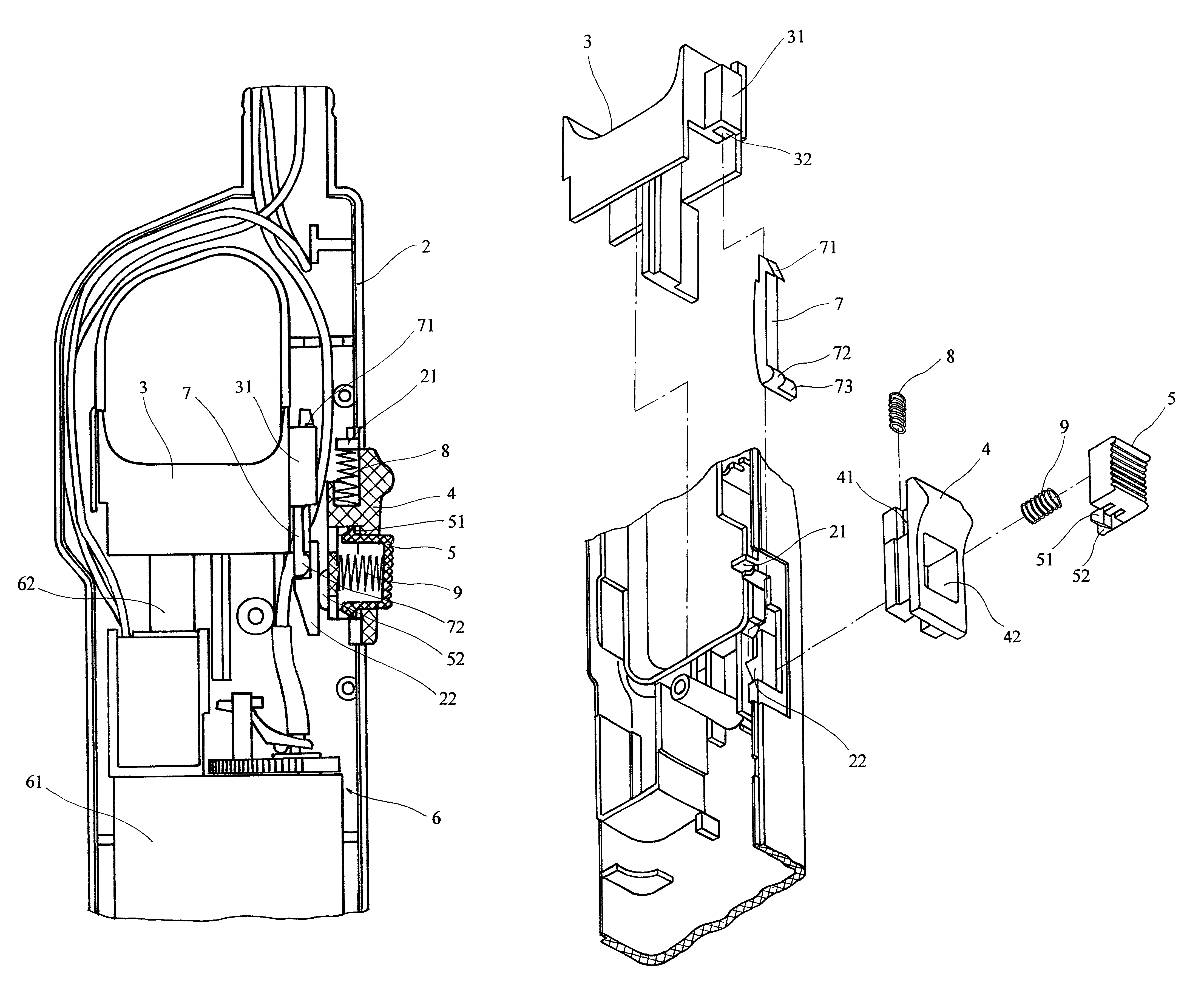
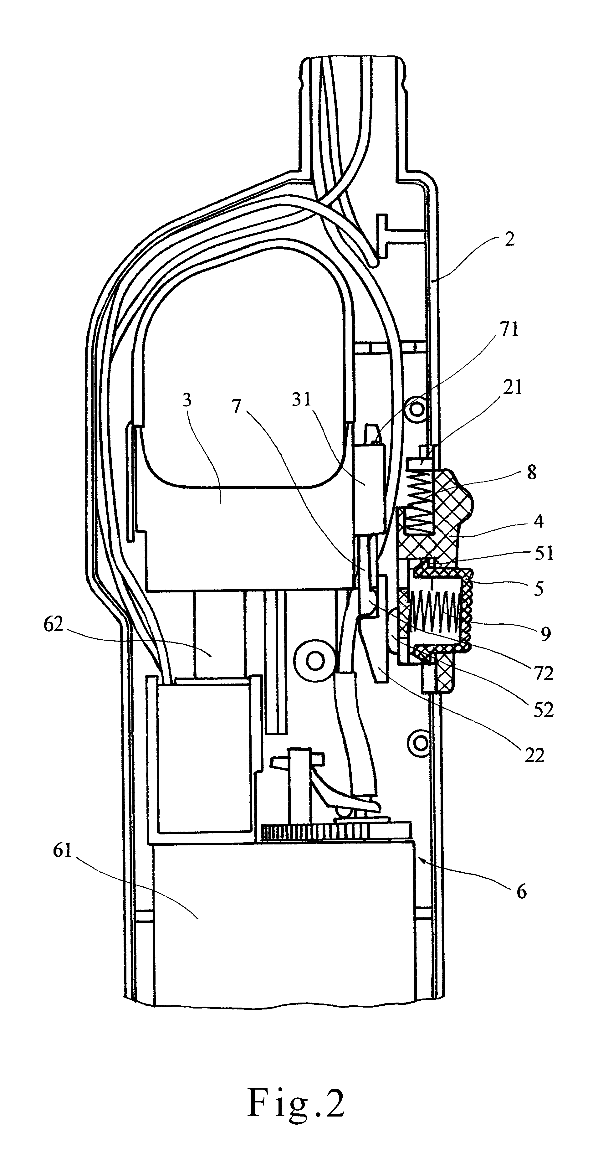
[0010]In natural condition, because the elastic limit bar is prevented by the barrier block on the inner wall of the gun body, the ignition trigger can't be pressed down. But when the push-button is pushed up and its button is pressed down, or when the button is pressed down and the push-button is pushed up, the protruding part of the button pushes the end of the elastic limit bar to make it distort and deflect from the barrier block on the inner wall of the gun body. Thereby people can relief the locking situation of the ignition trigger and press it down to fire the flammable gas.
[0011]Because the apparatus of this invention can fire the flammable gas only by doing the two compound actions i.e. pressing down the button and pushing up the push-button. Adults can accomplish the two compound actions with thumb in turn. It still can be used conveniently and flexibly. Children can't learn the arcanum of this apparatus even they observe slinkingly because of the concealedness of the operation action. So this invention can further improve the safety of the ignitor.

Problems solved by technology

However, because it is very easy to be operated and it is like a toy by the appearance and the function and the operating method, children are in favor of playing with it and can fire it by misplay easily that will bring potential danger.
But many users forget to reset the ignition trigger to “off” position after igniting, so the locking switch has no function.
It is very easy for children to learn this, so its security is not perfect.

Method used


Image

  • Igniter with a push-button and an elastic bar
  • Igniter with a push-button and an elastic bar
  • Igniter with a push-button and an elastic bar

Examples


Embodiment Construction

[0017]The invention will be described more details with reference to the accompanying drawing.

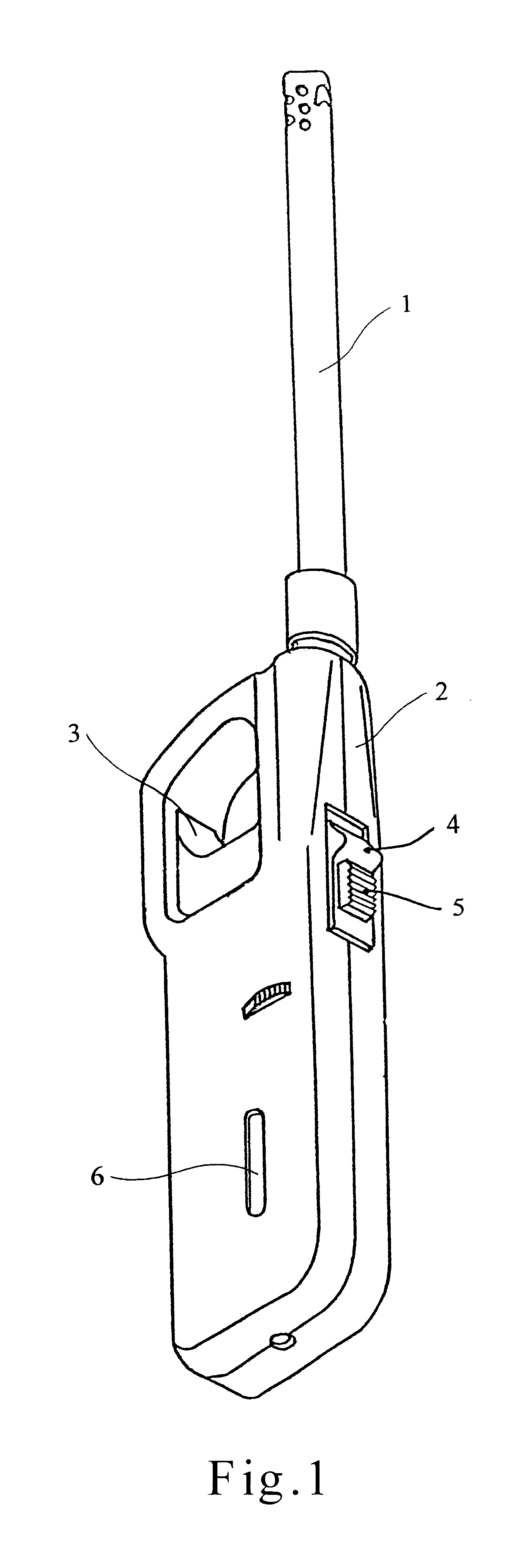
[0018]As shown in FIGS. 1 to 5, the igniter with a safety unit comprises a gun body 2 which can be gripped and a barrel 1 extending outside, reference to FIG. 1. A gas-fired tank and an ignition subassembly 6 consisted of a pneumatic valve unit 61 and a piezolighter 62 are arranged in the gun body 2. An ignition trigger 3 is arranged at the mid-portion of the gun body 2 and partially protrudes out of the gun body 2. A socket body 31 is arranged on one side of the ignition trigger 3 towards the backside of the gun body. An elastic limit bar 7 inserts into a longitudinal hole 32 of the socket body 31 from up to down and engages with it. The elastic limit bar 7 has a hook 71 which can chuck the upper end of the socket body 31. In natural condition, the second end 73 of the elastic limit bar 7 keeps against lower barrier block 22 which is integrated with the inner wall of the gun body 2 by moul...


PUM


Abstract

Igniter with safety unit, the safety unit comprises a push-button that is arranged at the backside of the gun body and partially protrudes out of the gun body, it can be pushed forward and return relative to the gun body; a elastic limit bar that is arranged at the side of the part of the ignition trigger that is towards the backside of the gun body, in natural condition, its end keeps against a barrier block which is integrated with the inner wall of the gun body; a button that is arranged in the push-button and protrudes out of the push-button, it can be pressed into the gun body and return. A protruding part arranged on the button's inner side protrudes towards a mid-portion of the gun body. In natural condition, the protruding part is towards the blank part, but when the push-button is in pushed up condition, the protruding part is near the end of the elastic limit bar and opposite to it. Thereby, if the button is pressed down, the protruding part of the button pushes the end of the elastic limit bar to make it distort and deflect from the barrier block on the inner wall of the gun body. The locking situation of the ignition trigger can be released. The apparatus can fire the flammable gas only by doing the two compound actions i.e. pressing down the button and pushing up the push-button simultaneously, thus further improving the safety of the ignitor.

Description

FIELD OF INVENTION[0001]This invention relates to ignitor, in particularly, to one with a safety unit that can prevent it from being fired easily by children by misplay.BACKGROUND OF THE INVENTION[0002]The existing igniter generally comprises a gun body which can be gripped and a barrel extending away from the upper part of the gun body. A gas-fired tank and a pneumatic valve unit and a piezolighter and an ignition trigger are arranged in the gun body. Liquefied flammable gas is contained in the gas-fired tank. One can press the ignition trigger during operation, thereafter the pneumatic valve opens, at the same time, the piezolighter produces electrical spark at the port of the igniter barrel by wire to fire the flammable gas transported to the port of the igniter barrel through a transfer pipe. If people pressed the ignition trigger continuously without unloosing it, a burning flame will continue at the port of the gun barrel. So it is very convenient to operate this ignitor. Sinc...

Claims


Application Information

Patent Timeline
Patent Type & Authority Patents(United States)
IPC IPC(8): F23Q2/16F23Q2/00
CPCF23Q2/164
Inventor JUDENG, ZHANG
Owner JUDENG ZHANG
Learn More