Optimized solid/liquid separation system for multiphase converters

a solid/liquid separation and converter technology, applied in separation processes, liquid degasification, filtration separation, etc., can solve the problems of increasing the cost of natural gas, reducing the natural resource of crude oil used for liquid fuels such as gasoline and middle distillates, and presenting technological challenges in transportation. , to achieve the effect of reducing the cost of production, and being efficient in product recovery

Inactive Publication Date: 2005-05-03
CONOCOPHILLIPS CO
View PDF23 Cites 19 Cited by
  • Summary
  • Abstract
  • Description
  • Claims
  • Application Information

AI Technical Summary

Benefits of technology

[0017]The filtration method according to this invention is different than a method known as cross-flow filtration, where a cake is not needed, and furthermore is avoided or ‘barely’ tolerated. Moreover, in this invention the resulting fluxes are much higher than the fluxes associated with cross-flow filtration, thereby making it more efficient in product recovery and more cost effective. This filtration method is also different from a method known as dead-end filtration, as the filtration in this invention can be operated in a continuous manner and is well suited for high solid content.
[0018]The embodiments of the present invention provide a filtration system that provides enhanced filter life and performance while being resistant to the deleterious effects of fine catalyst particles bypassing the filter medium and contaminating the liquid products. The enhanced filter life and performance results at least in part from the less-frequent use of backwashing or blowback. Typically, at the beginning of a backwash, some fines can pass through the substrate, resulting in an increased probability of clogging the substrate and causing a degradation in the quality of the filtrate in terms of solids content. By minimizing the frequency of backwashes, the presence of fines inside the substrate is less prominent and therefore the probability of fines into the filtrate is lessened. The present invention also relates to the filtrate product obtained from such methods, which is characterized by an improved quality and a very small solid content.
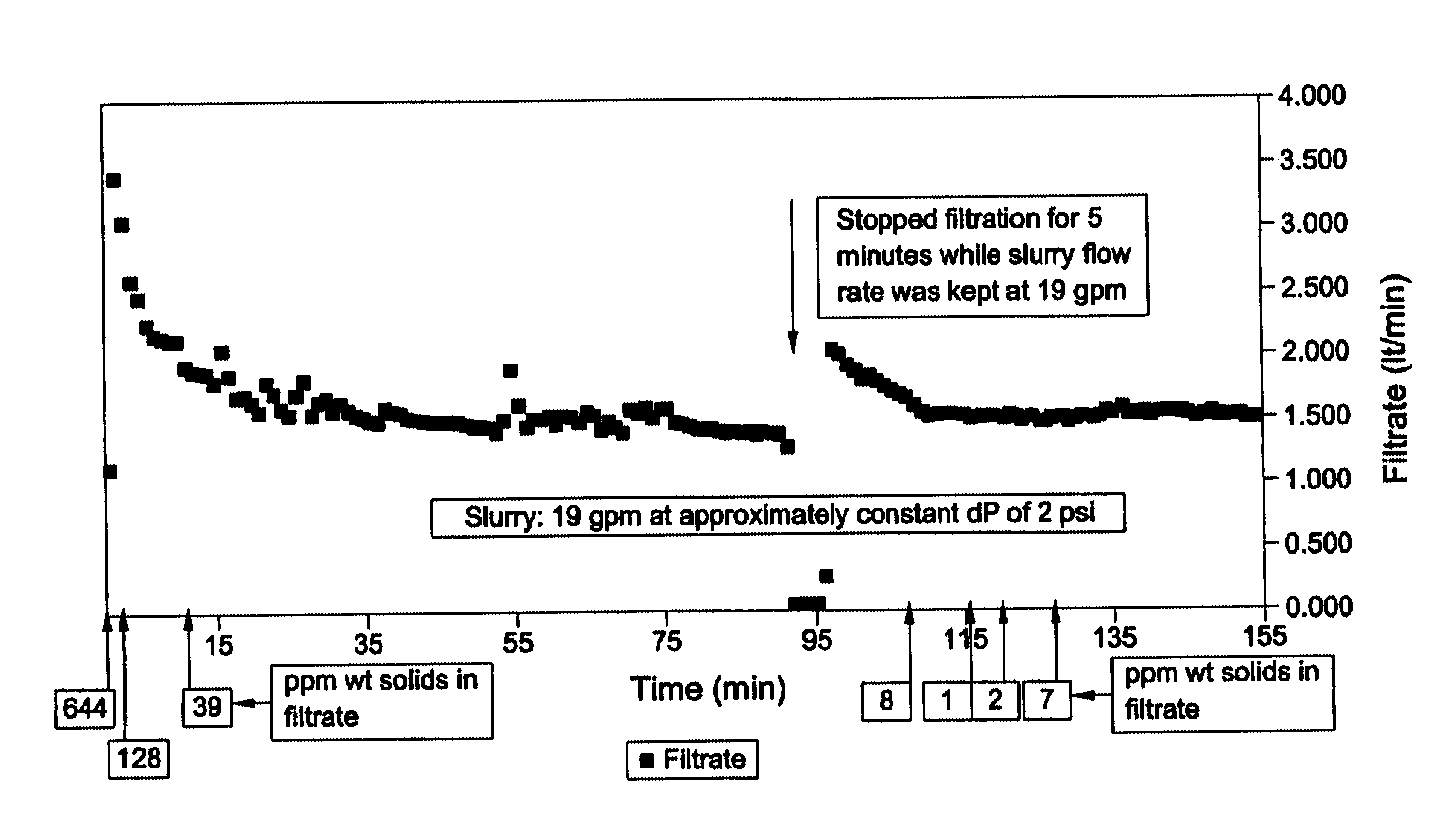
[0019]When the filtrate flow rate or flux (flux defined as filtrate flow rate divided by the area of substrate) is below a determined level, it may become necessary to restore the filtrate flow to a more desirable value. The restoration of filtrate flow can be achieved by reducing the cake thickness. To remove some or all of the cake, any known cleaning method or combination of methods which use a reverse flow of fluid (gas, liquid, or combinations) such as backwashing or blowback can be used. Alternatively, the applicants discovered a novel technique for cleaning the substrate that comprises stopping the filtration flow for a short period of time, maintaining constant slurry flow through the slurry chamber, and resuming filtration rate to a more desirable level. This technique will result in a reduction or minimization of the backwash frequency. Any combination of these cleaning methods or any alternation of techniques is also contemplated in this invention.
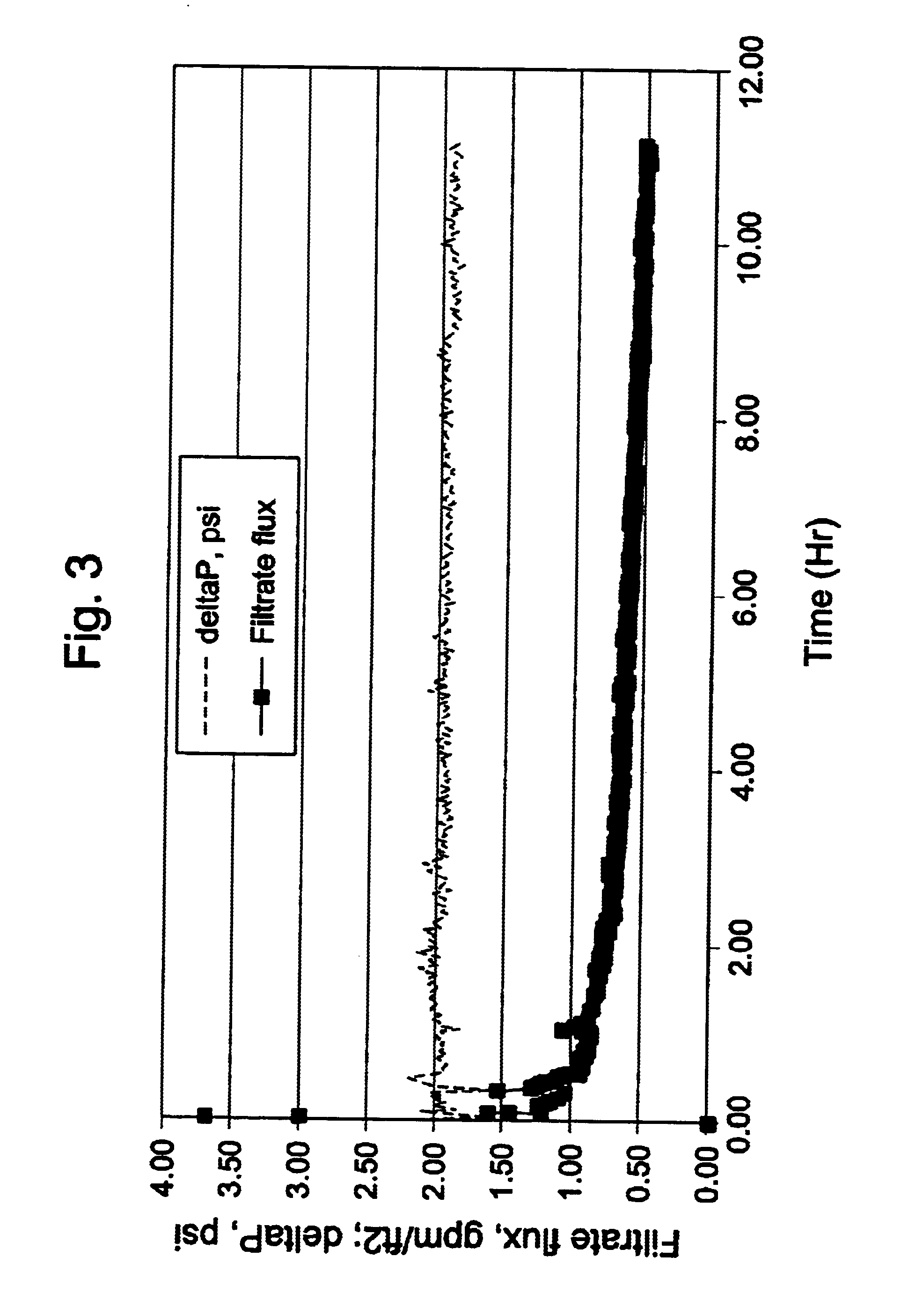
[0020]As the filter cake thickness increases, the flow area through the slurry chamber in which the slurry enters decreases, causing a corresponding increase in the slurry velocity and an increase in pressure differential across the filter medium, while decreasing the filtration rate. In this condition, the flow rate of slurry can be increased to further increase the slurry velocity so as to erode the filter cake and decrease the cake thickness. It has been discovered that a velocity of greater than 5 feet / second (ft / sec) across the filter cake will result in a loss of cake thickness and stability. Therefore, by periodically increasing the linear velocity of the slurry entering the filtration system for a short period of time, the cake thickness will decrease, thus increasing the filtrate flow through the filter medium and resulting in an extended period of time between backwashes or blowbacks. By maintaining a slurry velocity of at least 0.3 ft / sec and not more than 5 ft / sec combined with a pressure differential across the filter medium of not more than 30 psi (207 kPa), preferably not more than 15 psi (103 kPa), and most preferably not more than 5 psi (34 kPa), the filtration cycle time can be extended to several hours between cleanings, such as backwashes, blowbacks, or other cleaning techniques.
[0021]A preferable filtration system provides for a filtration rate of at least 0.2 gallons per minute per square foot of filter area, or gpm / ft2, (about 490 L / m2 / hr) and as much as 8 gpm / ft2 (about 19,600 L / m2hr) or more. In some embodiments the filtration rate is greater than 0.4 gpm / ft2, preferably between 0.4 gpm / ft2 to 8.0 gpm / ft2. The slurry exiting the filtration system through the outlet has between 1 and 30%, and preferably between 2 and 10%, less liquid content than the slurry entering the system. The production and efficiency of the filtration system can be controlled by varying the flow rate of slurry through the system and / or the pressure differential between the slurry chamber and the filtrate chamber.
[0024]Thus, the present invention comprises a combination of features and advantages that enable it to substantially increase efficiency of removing liquid products from a slurry having a high solids concentration. These and various other characteristics and advantages of the present invention will be readily apparent to those skilled in the art upon reading the following detailed description of the preferred embodiments of the invention and by referring to the accompanying drawings.

Problems solved by technology

Wells that provide natural gas are often remote from locations with a demand for the consumption of the natural gas.
This transportation presents technological challenges due, in part, to the large volume occupied by a gas.
However, this contributes to the final cost of the natural gas.
Further, naturally occurring sources of crude oil used for liquid fuels such as gasoline and middle distillates have been decreasing and supplies are not expected to meet demand in the coming years.
One problem with the removal of usable liquid products, however, is that catalyst particles are dispersed in the liquid and must be separated from the slurry.
These methods have been developed for separating catalyst particles from Fischer-Tropsch wax but have proved less than ideal or were not deemed commercially viable.
In a commercial SBCR, the severe hydrodynamic conditions inside the reactor, coupled with the desired long lifetime of the catalytic material, can result in catalyst attrition.
The presence of fines in the reactor tends to greatly reduce the effectiveness of the catalyst-liquid separation system.
The higher the backwashing frequency the poorer the quality of the filtrate.

Method used


Image

  • Optimized solid/liquid separation system for multiphase converters
  • Optimized solid/liquid separation system for multiphase converters
  • Optimized solid/liquid separation system for multiphase converters

Examples


examples

[0053]Experiments were conducted using the laboratory setup 500 described in FIG. 2. A slurry was formed in a slurry mixing tank 510. The slurry was a mixture of model wax (n-decane) and solid particles of a cobalt-based catalyst. The cobalt-based catalyst is supported on an alumina material and is active in the Fischer-Tropsch reaction. The solid concentration in the slurry was approximately 23-25% by weight (or about 10% by volume). The catalyst particle size when the catalyst was fresh and first loaded in the slurry mixing tank 510, was in the range of 20 to 150 microns An agitator (not shown) placed inside slurry mixing tank 510 was used to maintain the solids suspended in the slurry. A slurry pump 520 sent a portion of the slurry from slurry mixing tank 510 either back to the slurry mixing tank 510 or to a filtration housing 540. A valve (not shown) was used to direct the slurry flow to the appropriate location. The filtration housing 540 comprises a substrate. The substrate wa...


PUM

PropertyMeasurementUnit
weight percentaaaaaaaaaa
number average particle sizeaaaaaaaaaa

Abstract

Methods for producing clean liquid / wax products from a slurry used in a Fischer-Tropsch reactor are disclosed. In general, one embodiment of the present invention comprises a solid / liquid filtration system having a filter medium comprising a substrate and a filter cake deposited on the substrate, wherein the filter cake is generated by deposition of solids from the slurry. The thickness of the filter cake can be maintained within a desired range by controlling the slurry velocity and / or the pressure differential across the filter medium. This invention relates to a method of operation of such filtration system which increases filtration cycle time and improved filtrate quality resulting in very low solid content in filtrate.

Description

CROSS-REFERENCE TO RELATED APPLICATIONS[0001]The present application claims priority to U.S. Provisional Application No. 60 / 372,961, filed Apr. 16, 2002, titled “Solid / Liquid Separation System for Multiphase Converters,” the entirety of which is hereby incorporated by reference herein for all purposes.STATEMENT REGARDING FEDERALLY SPONSORED RESEARCH OR DEVELOPMENT[0002]Not applicable.TECHNICAL FIELD OF THE INVENTION[0003]The present invention relates generally to methods and apparatus for removing liquid / wax products from a slurry used in a Fischer-Tropsch reactor. Particularly this invention relates to methods of operating a filtration system with better filtrate quality, and longer filtration cycle times. The present invention also includes a method to remove the cake, at least partially, without compromising the filtrate quality during the next filtration cycle and minimizing the need of traditional backwash or blowback cleaning methods.BACKGROUND OF THE INVENTION[0004]Natural ga...

Claims


Application Information

Patent Timeline
Patent Type & Authority Patents(United States)
IPC IPC(8): B01D37/00B01D37/02B01D29/15
CPCB01D29/15B01D37/02B01D29/60B01D37/043
Inventor MOHEDAS, SERGIO R.ESPINOZA, RAFAEL L.JACK, DOUG S.ODUEYUNGBO, OLUWASEI A.ORTEGO, JR., JAMES DALE
Owner CONOCOPHILLIPS CO
Why Eureka
Try Eureka