Solid/liquid separation system for multiphase converters

a multi-phase converter and solid/liquid separation technology, which is applied in the direction of filtration separation, separation process, moving filter element filter, etc., can solve the problems of reducing the efficiency of the separation system, the most difficult separation task, and the catalytic wax must be separated

Inactive Publication Date: 2005-02-03
CONOCOPHILLIPS CO
View PDF19 Cites 35 Cited by
  • Summary
  • Abstract
  • Description
  • Claims
  • Application Information

AI Technical Summary

Benefits of technology

The filtration method according to the preferred embodiments is different than a method known as cross-flow filtration, where a cake is not needed, and furthermore is avoided or ‘barely’ tolerated. Moreover, the resulting filtrate fluxes are much higher than the fluxes associated with cross-flow filtration, thereby making it more efficient in product recovery and more cost effective. This filtration method is also different from a method known as dead-end filtration, where the operation is not continuous and is not well suited for Fischer-Tropsch applications. Another key feature of the preferred embodiments is that the slurry flows into and out of the slurry chamber while a fraction of the liquid in the slurry is withdrawn as filtrate, such that the filtration system can operate in a continuous, as opposed to batch flow, mode.
A preferable separation system provides for at least 0.2 gallons per minute per square foot of substrate area and as much as 2 gallons per minute per square foot, or more. In the present invention, the amount of filtrate per unit time and per unit of substrate area is refer also as flux. The slurry exiting the separation system through the outlet has between 1 and 30%, and preferably between 2 and 10%, less liquid content than the slurry entering the system. In some other embodiments, the slurry exiting the separation system through the outlet has between 3 and 10% less liquid content than the slurry entering the system. The production and efficiency of the separation system can be controlled by varying the flow rate of slurry through the system and the differential pressure between the slurry chamber and the filtrate chamber.
Thus, the present invention comprises a combination of features and advantages that enable it to substantially increase efficiency of removing liquid products from a slurry having a high solids concentration. These and various other characteristics and advantages of the present invention will be readily apparent to those skilled in the art upon reading the following detailed description of the preferred embodiments of the invention and by referring to the accompanying drawings.

Problems solved by technology

The problem with wax removal is that catalyst in the wax must be separated from the slurry and returned to the reactor to maintain a constant inventory of catalyst in the reactor.
The separation task is most challenging when the catalyst particles break down during operation to produce “fines” which could be as small as sub-micron in size.
Independent of the catalyst-wax separation systems being used (i.e. centrifugation, settling, filtration, hydrocyclones, or magnetic separation), the presence of ultra-fine particles decreases the efficiency of the separation system.
When a cake is allowed to form on a substrate, its continuous growth will result in a lower filtrate flux unless continuous backwash cycles are performed, therefore lowering the overall efficiency of the filtration system.

Method used


Image

  • Solid/liquid separation system for multiphase converters
  • Solid/liquid separation system for multiphase converters
  • Solid/liquid separation system for multiphase converters

Examples


example 1

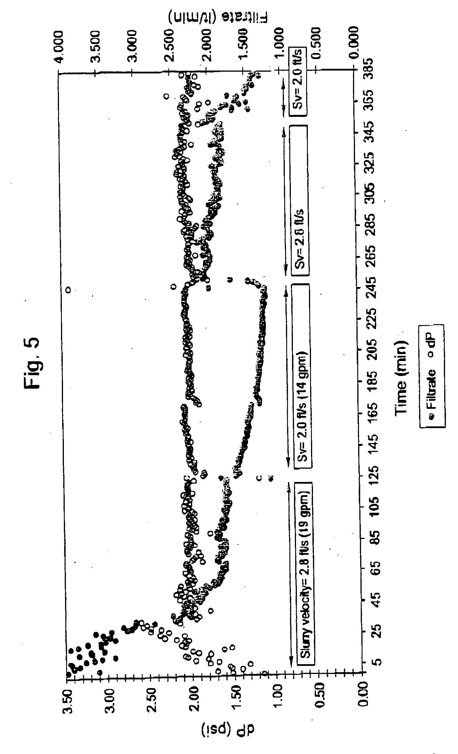
In FIG. 5, the slurry flow in the filter housing for this particular example was cycled at two different rates: 19 and 14 gallons per minute (gpm), which is equivalent to a slurry linear velocity in the filter housing about of 2.8 and 2 ft / s respectively. The pressure differential across the filter medium was kept approximately constant at 2 psi by modifying the filtrate flow rate. FIG. 5 shows the effect of the slurry velocity on the filtrate flow across the filter medium. Different slurry velocities typically form cakes of different thickness around the substrate at the same pressure differential across the filter medium; therefore these different cakes exhibit different characteristics like thickness and permeability, which lead to different filtrate flows across the filter medium.

Thus, in the example of FIG. 5 for instance, the filtrate flow rate had a tendency to stabilize between 1.75 to 2.00 L / min (0.46-0.53 gpm) at a slurry velocity in the housing of 2.8 ft / s; and at a sl...

example 2

In a similar experiment to Example 1, the slurry flow in the filter housing for this particular example was cycled at two different rates: 8 and 14 gallons per minute (gpm), which is equivalent to a linear velocity in the filter housing of 1.2 and 2.0 ft / s respectively. The pressure differential across the filter medium was kept approximately constant at 3 psi by modifying the filtrate flow rate. Similarly to FIG. 5, FIG. 6 shows the effect of the slurry velocity on the filtrate flow across the filter medium. For instance, in this example, the filtrate flow rate stabilized around 0.8 to 1.2 L / min at a slurry velocity of 1.2 ft / s, and stabilized between 1.2 to 1.5 L / min at a slurry velocity of 2.0 ft / s. Therefore, it can be seen that the filtrate flow rate is dependent on the slurry velocity, which indicates that the cake thickness can be controlled by regulating the linear velocity of the slurry across the cake.

example 3

A further series of experiments were conducted in the same manner as described in Example 1 using different substrates such as sintered woven wire-mesh (substrates A and B) and sintered powder metal membrane (substrate C), all of different manufactures. The filtrate flow rate (L / min) using a pressure differential of 2 psi and a slurry velocity of 2.8 ft / s (slurry flow rate of 19 gpm) during a 60-minute period for each substrate are reported in Table 1 as well as breakthrough of solid content observed in the filtrate at the onset of cake formation. All three substrates tested exhibited similar overall behavior proving that the filtrate flux in this invention is basically independent of the technology of forming the substrate. The filtrate quality was measured during the experiments showing very good performance. The amount of solids in the filtrate was most of the time below 50 ppm by weight, more typically less than 15 ppm by weight of solid, and often less than 10 ppm by weight, e...


PUM

PropertyMeasurementUnit
weight percentaaaaaaaaaa
number average particle sizeaaaaaaaaaa

Abstract

Methods and apparatus for removing wax products from a slurry used in a Fischer-Tropsch reactor. The preferred embodiments of the present invention are characterized by a solid / liquid separation system that removes liquid products from a slurry by drawing the fluid across a filter medium composed of a filter cake disposed on a substrate. In the preferred embodiments, the filter cake is desirable and performs the majority of the filtration. In certain embodiments, the filter medium is disposed in a filter housing where slurry flows parallel to the longitudinal axis of the filter medium from and inlet to an outlet. The characteristics or properties of the cake, which will effect the performance of the solid / liquid separation system, can be controlled by regulating the velocity of the slurry flowing across the cake, where the velocity may be regulated by adjusting the slurry flow through the filter housing or may be self-regulated by changing slurry velocities influenced by the design of the filter housing.

Description

STATEMENT REGARDING FEDERALLY SPONSORED RESEARCH OR DEVELOPMENT Not applicable. TECHNICAL FIELD OF THE INVENTION The present invention relates generally to methods and apparatus for removing liquid / wax products from a slurry used in a Fischer-Tropsch reactor. Particularly this invention relates to a method of operation of a filtration system with greater filtration fluxes, better filtrate quality, and longer filtration cycle times. The filtration system uses a cake as a filter, and the thickness of the cake is self-regulating by adjustment in slurry velocity within desired ranges, while maintaining desirable pressure differential. BACKGROUND OF THE INVENTION A Fischer-Tropsch reaction generally entails contacting a stream of synthesis gas with a catalyst under temperature and pressure conditions that allow the synthesis gas to react and form hydrocarbons. More specifically, the Fischer-Tropsch reaction is the catalytic hydrogenation of carbon monoxide to produce any of a variety ...

Claims


Application Information

Patent Timeline
Patent Type & Authority Applications(United States)
IPC IPC(8): B01D29/15B01D37/02
CPCB01D29/15B01D37/02B01D29/60B01D37/043
Inventor ESPINOZA, RAFAEL L.MOHEDAS, SERGIO R.JACK, DOUG S.ODUEYUNGBO, OLUWASEYI A.ORTEGO, JAMES DALE JR.
Owner CONOCOPHILLIPS CO
Why Eureka
Try Eureka