Curable flame retardant epoxy compositions

a flame retardant epoxy and composition technology, applied in the field of cureable flame retardant epoxy resin compositions, can solve the problems of difficult processing of brominated epoxy composites used in printed circuit board fabrication, difficult to drill the holes of brominated epoxy composites, and reduce the fracture resistance of these materials, so as to increase the fracture resistance and flame retardance of epoxy resins, reduce the modulus, and increase the fracture resistance

Inactive Publication Date: 2005-05-03
RGT UNIV OF MINNESOTA
View PDF15 Cites 172 Cited by
  • Summary
  • Abstract
  • Description
  • Claims
  • Application Information

AI Technical Summary

Benefits of technology

[0092]An advantage of the present invention is that epoxy compositions containing brominated epoxies, which are known to be very brittle and subject to drilling problems, can now be used in microelectronic applications, because with the addition of block copolymers with the correct composition and architecture to induce self-assemble into a worm-like morphology, it should be possible to circumvent this drilling problem with the increase in fracture resistance of these materials.
[0093]In the dilute limit, block copolymers self-assemble into disordered worm-like micelles or spherical micelles. Each of these morphologies can be generated in cured brominated and non-brominated epoxy resins and representative images are shown in FIGS. 1-2. Spherical micelles, shown in FIGS. 2A and 2B, contain a hydrocarbon core surrounded by an epoxy compatible corona. In contrast, cylindrical (“worm-like”) micelles, shown in FIGS. 1A and 1B, are long, thin tubes where the epoxy miscible block forms a corona shielding the epoxy immiscible cylinder interior. The two morphologies are formed by the PEO-PEP and P(MMA-ran-GMA)-PEHMA diblock copolymers, where the equilibrium phase is largely determined by the block copolymer asymmetry (i.e., the relative length of the epoxy miscible block). The morphology is established in the initial unreacted block copolymer-resin mixture, which becomes permanently fixed during the curing stage. The epoxy resin used for FIGS. 1-3 is a 3:1 blend of D.E.R. 383 / D.E.R. 560 epoxy formulation.
[0094]Modifying an epoxy resin with a block copolymer may reduce the modulus, although not significantly. However, FIG. 4 shows that the strain energy release rate, Gc, of worm-like modified epoxies (for example, D.E.R. 560) increases dramatically even as the amount of brominated epoxy in the formulation increases to 50 weight %. FIG. 4 also shows the fracture resistance of neat epoxy resins, for example, D.E.R.560. Neat resins may also include amine cured bisphenol A epoxy (BPA348, Mw=348 g / mole, cured with 4,4′-methylenedianiline, MDA). Worm-like micelles gave the best improvements in Gc, as shown in FIG. 4.
[0095]The present invention demonstrates a way to simultaneously increase the fracture resistance and flame retardance of epoxy resins. The present discovery has important implications for both the microelectronic and aircraft industries where regulations mandate the use of flame retardant epoxy resins. Typically, increasing the flame retardance of an epoxy resin reduces its fracture resistance, making it difficult to process these materials into finished products. For example, a major problem in the microelectronics industry is the drillability of brominated epoxy composites used in printed circuit board fabrication. This deficiency is evident in the inability to machine test samples, for example, from neat 1:1 DER 383 / DER 560 formulations. The materials of the present invention are easy to process since self-assembly occurs spontaneously upon blending and the resulting viscosity is marginally affected at the low block copolymer loadings described here.
[0096]Often an increase in fracture resistance comes at the expense of the use temperature and modulus. In the present invention, both fracture resistance and flame retardance is achieved without a major reduction in the modulus and with an increase in the use temperature. Thus, a way has been found to circumvent the typical trade-off in epoxies where toughness comes at the expense of other desirable properties. For example, some of the toughest resins of the present invention have a modulus reduction of, for example, only 5 to 10 percent while their Tg increases, for example, up to about 16%.
[0097]Clearly, the materials of the present invention do not follow the patterns described in the epoxy toughening literature where it was previously concluded that some epoxies were too brittle to toughen effectively.

Problems solved by technology

However, increasing the flame retardance of an epoxy resin, by brominating an epoxy resin, reduces its fracture resistance, making it difficult to process these materials into finished products.
For example, a major problem in the electronics industry is the drillability of brominated epoxy composites used in printed circuit board fabrication, because brominated epoxy composites are known to be very brittle.
Thus, while bromination of epoxy compositions is necessary to improve the flame resistance of the epoxies, particularly when such epoxies are to be used in microelectronic applications, brominated epoxy resin materials used in microelectronic applications easily shatter during drilling procedures and, in turn, limit their applications.
These bromine-free epoxy resins also have the disadvantage of being brittle and may be difficult to drill during printed circuit board fabrication.
Epoxies in general are known to be very difficult to toughen and some epoxies are too brittle to toughen effectively.
Moreover, increasing the fracture toughness of brittle epoxies often comes at the expense of modulus and use temperature, creating unacceptable limits on the applicability of these resins.

Method used


Image

  • Curable flame retardant epoxy compositions
  • Curable flame retardant epoxy compositions
  • Curable flame retardant epoxy compositions

Examples


example 1

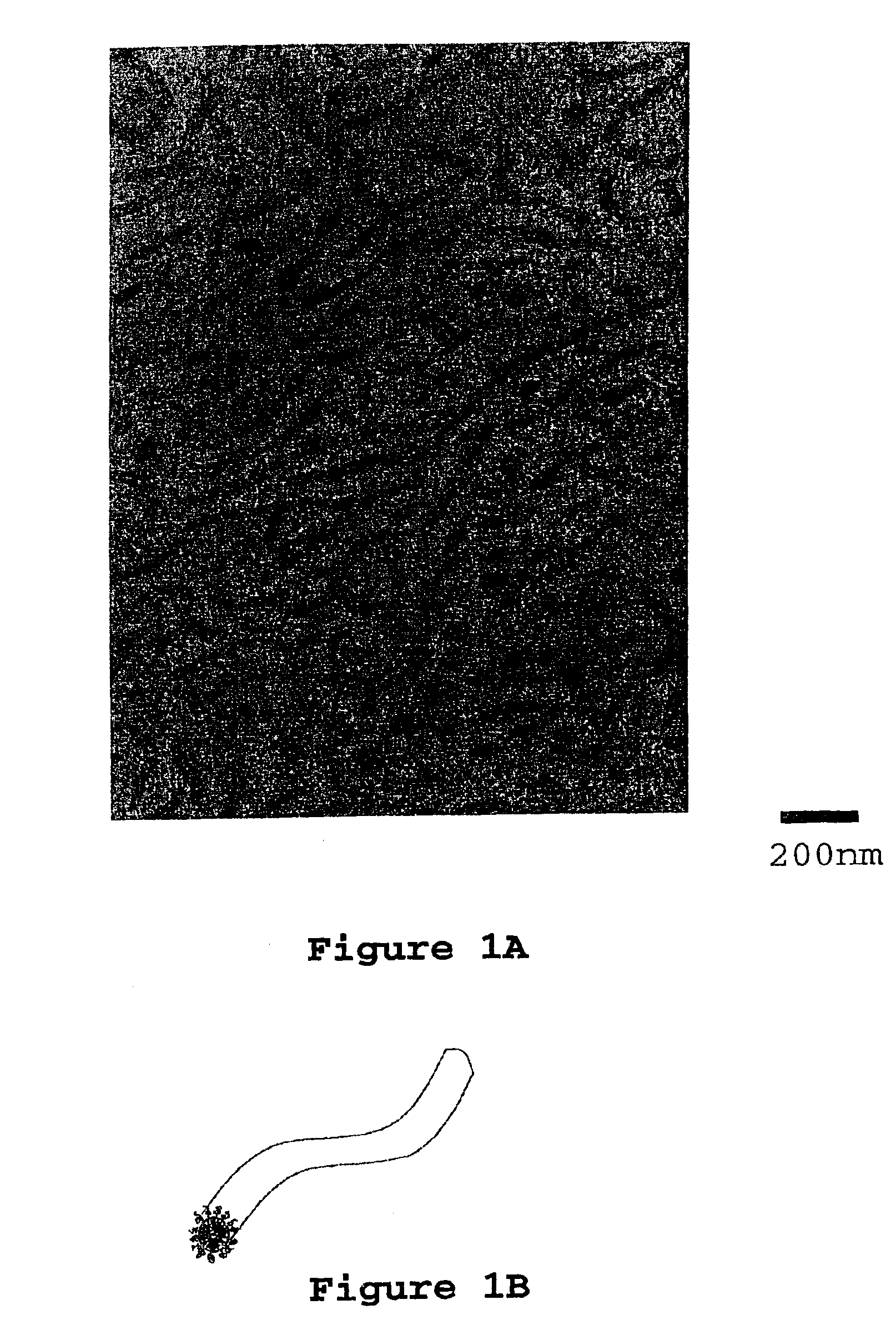
[0117]Two grams of PEO-PEP block copolymer (ƒPEO=0.25, Mn=8,000 g / mole, Mw / Mn=1.04) were added to 24.00 grams D.E.R. 383 in a round bottom flask. 23 mL of acetone was added to the flask and the contents were stirred until the block copolymer was completely dissolved (approximately two weeks). Then 14.00 grams of phenol novolac were added to the flask and the contents of the flask stirred until the phenol novolac dissolved. The flask was attached to a vacuum line using a 24 / 40 connector. The acetone solvent was slowly removed at room temperature until any resultant foaming subsided (thirty minutes). An oil bath was placed around the flask and a temperature was set to 50° C. The solvent was removed for 1 hour at 50° C. and then the temperature was increased to 75° C. (1 hour), and then to 100° C. (thirty minutes). The oil bath temperature was set to 150° C. and, after waiting for 10 minutes, the flask was disconnected from the vacuum line. The epoxy and block copolymer blend was poure...

example 2

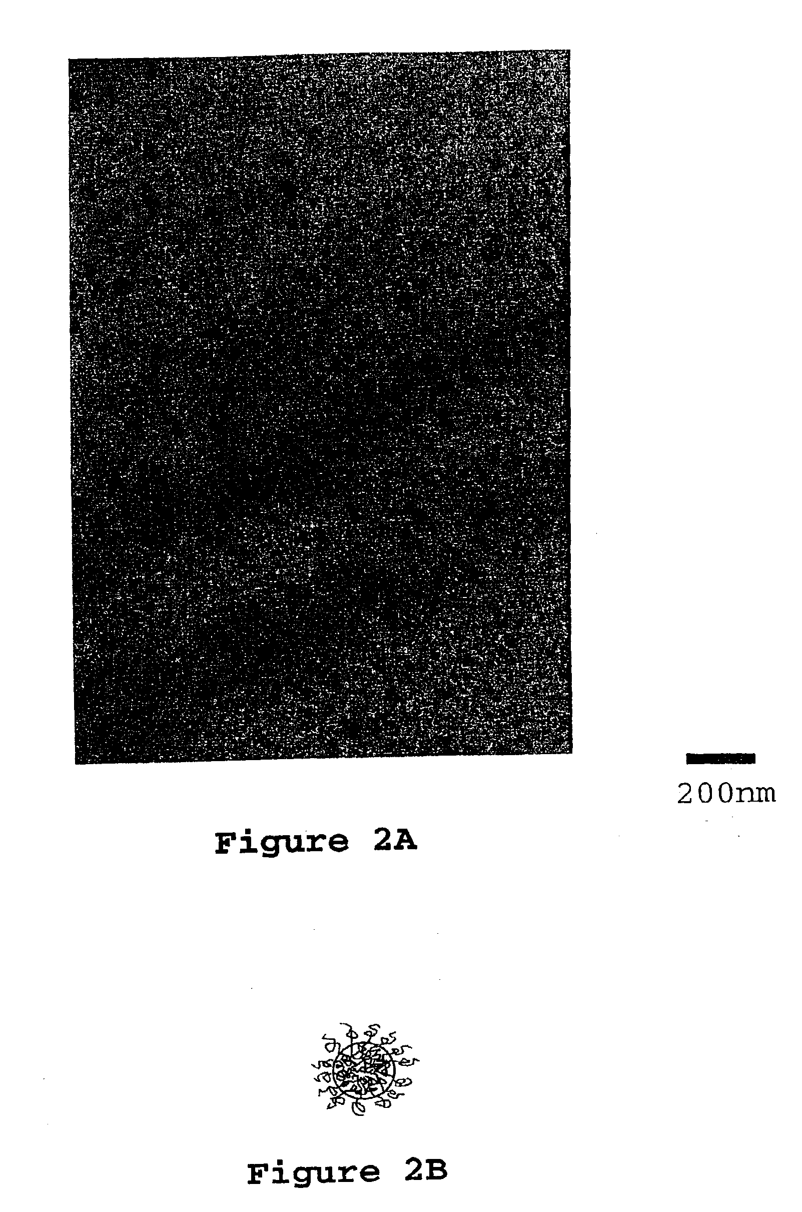
[0119]Two grams of PEO-PEP block copolymer (∫PEO=0.25, Mn=8,000 g / mole, Mw / Mm=1.04) were added to 23 mL acetone and stirred until the polymer was dissolved (two days). 24.00 Grams D.E.R. 383 were added to the flask and the contents of the flask stirred until dissolved (one to two days). Then 14.00 grams of phenol novolac were added and stirred until dissolved. The flask was attached to a vacuum line using a 24 / 40 connector and the solvent was slowly removed at room temperature until any resultant foaming subsided (thirty minutes). An oil bath was placed around the flask and the temperature was set to 50° C. The solvent was removed for 1 hour at 50° C. and then the temperature was increased to 75° C. (1 hour), and then to 100° C. (thirty minutes). The oil bath temperature was set to 150° C. and, after waiting 10 minutes, the flask was disconnected from the vacuum line. The epoxy and block copolymer blend was poured into a 4 mm thick rectangular mold (preheated to 150° C.) coated with...

example 3

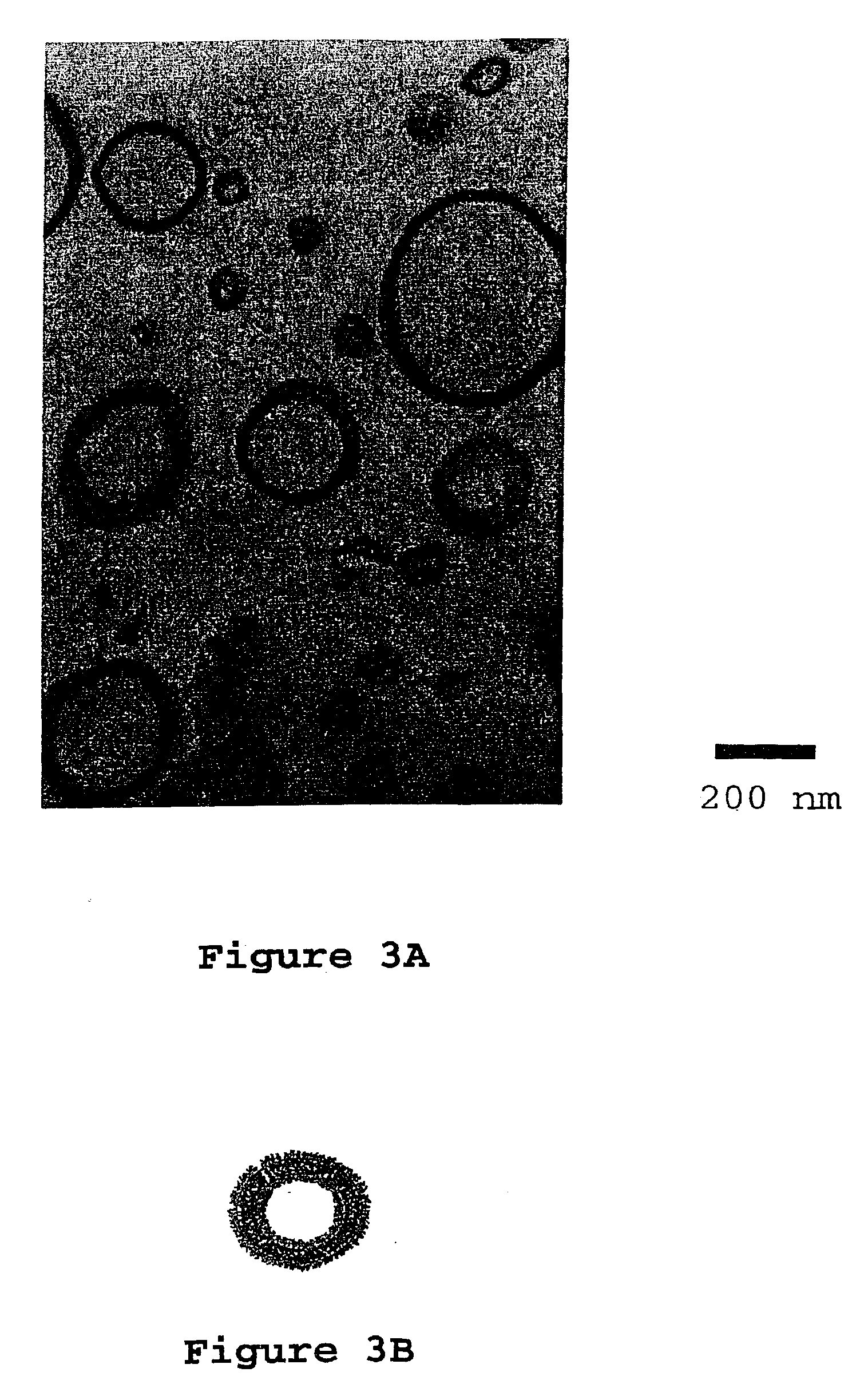
[0121]Two grams of PEO-PEP block copolymer ƒPEO=0.25, Mn=8,000 g / mole, Mw / Mn=1.04) were added to 19.05 grams D.E.R. 383 and 6.35 grams D.E.R. 560 in a round bottom flask. 23 mL acetone was added to the flask and the contents of the flask stirred until the block copolymer was completely dissolved (approximately two weeks). Then 12.6 grams of phenol novolac were added and stirred until dissolved. The flask was attached to a vacuum line using a 24 / 40 connector and the solvent was slowly removed at room temperature until the resultant foaming subsided (thirty minutes). An oil bath was placed around the flask and the temperature was set to 50° C. The solvent was removed for 1 hour at 50° C. and then the temperature was increased to 75° C. (1 hour), and then to 100° C. (thirty minutes). The oil bath temperature was set to 150° C. and, after waiting for 10 minutes, the flask was disconnected from the vacuum line. The epoxy and block copolymer blend was poured into 4 mm thick rectangular mo...


PUM

PropertyMeasurementUnit
weight percentaaaaaaaaaa
polydispersityaaaaaaaaaa
temperaturesaaaaaaaaaa

Abstract

A curable flame retardant epoxy resin composition including (a) at least one flame retardant epoxy resin; (b) at least one amphiphilic block copolymer; and (c) a curing agent. Such components are present in the curable composition in the appropriate amounts and ratios such that, upon curing, the block copolymer self-assembles into a nano structure morphology, such as a worm-like micelle morphology. The resulting cured product made from the composition of the present invention has a remarkably increased high fracture resistance; and allows the use of flame retardant epoxies in applications where fracture resistance is an issue.

Description

FIELD OF THE INVENTION[0001]The present invention relates to a curable flame retardant epoxy resin composition with increased toughness and fracture resistance, which is particularly useful for preparing electrical laminates.BACKGROUND OF THE INVENTION[0002]Thermoset resins such as epoxy resins are commonly used, for example, in the microelectronic and aircraft industries. The regulations of both the microelectronic and aircraft industries mandate the use of flame retardant epoxy resins. Typically, flame retardant epoxy resins include epoxy resins containing bromine. However, increasing the flame retardance of an epoxy resin, by brominating an epoxy resin, reduces its fracture resistance, making it difficult to process these materials into finished products.[0003]For example, a major problem in the electronics industry is the drillability of brominated epoxy composites used in printed circuit board fabrication, because brominated epoxy composites are known to be very brittle. Thus, ...

Claims


Application Information

Patent Timeline
Patent Type & Authority Patents(United States)
IPC IPC(8): C08L71/00C08L59/00C08L71/02H05K1/03C08L63/00C08L33/06C08L33/10
CPCC08L59/00C08L63/00C08L71/02H05K1/0373C08G2650/58Y10T428/2971C08L33/10H05K1/0326H05K2201/0212C08L33/068Y10S428/901C08L2666/22C08L2666/24Y10T428/24994Y10T428/31515Y10T428/31522Y10T428/31511Y10T428/31529B82Y99/00
Inventor DEAN, JENNIFER M.BATES, FRANK S.PHAM, HA Q.VERGHESE, NIKHIL E.
Owner RGT UNIV OF MINNESOTA
Why Eureka
Try Eureka