Optical beam scanning device

a scanning device and optical beam technology, applied in the field of optical beam scanning devices, can solve the problems of large structure scale, inability to perfectly compensate for the shift of conventional devices, and increased number of folded mirrors mounted, so as to reduce the variation of the beam diameter of the main scanning direction and ensure the control time of the apc. , the effect of reducing the variation of the beam diameter

Inactive Publication Date: 2005-05-03
KK TOSHIBA +1
View PDF6 Cites 29 Cited by
  • Summary
  • Abstract
  • Description
  • Claims
  • Application Information

AI Technical Summary

Benefits of technology

[0017]The present invention provides an optical beam scanning device which is capable of reducing variations in a main scanning direction beam diameter depending on scanning positions and which enables high image quality while ensuring control time for APC in a light source device.

Problems solved by technology

Conventional devices do not compensate for this shift perfectly.
This results in a large scale of structure and an increased number of folded mirrors mounted in an optical beam scanning device.
As a result, costs are increased.
Nevertheless, the optical beam scanning device of Patent Reference 1 has a plurality of imaging lenses and thus the problem about an increased number of lenses may arise.

Method used


Image

  • Optical beam scanning device
  • Optical beam scanning device
  • Optical beam scanning device

Examples


first embodiment

(A) First Embodiment

[0036]Preferred embodiments of the optical beam scanning device of the present invention will be described hereinafter with reference to the drawings.

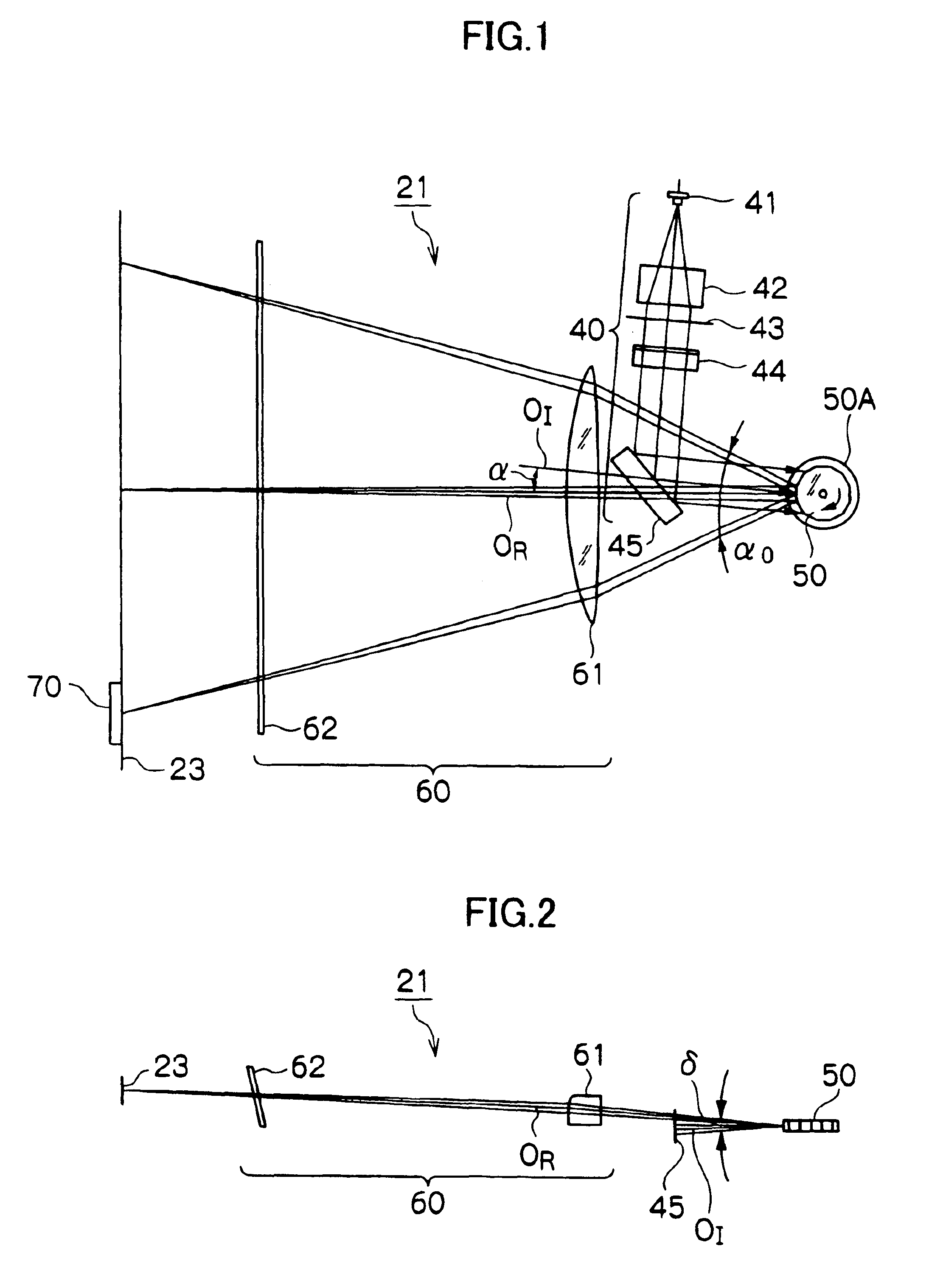
[0037]FIG. 1 shows a schematic plan view in which optical elements arranged between a light source (semiconductor laser element) 41 and a photosensitive drum (object to be scanned) 23 that are included in an optical beam scanning device 21 are seen from a main scanning direction and a folded state by folding mirrors is developed.

[0038]FIG. 2 shows a schematic cross-sectional view in which a cross-scanning direction perpendicular to the main scanning direction illustrated in FIG. 1 is depicted as a plane.

[0039]Referring to FIGS. 1 and 2, the optical beam scanning device 21 has a pre-deflection optical system 40, a polygon mirror 50 and an imaging optical system 60.

[0040]The pre-deflection optical system 40 has a semiconductor laser element (light source) 41, a luminous flux converting lens 42, an aperture 43, a cylin...

second embodiment

(B) Second Embodiment

[0134]Next, a description will be given, with reference to FIG. 17, of a modified example of imaging elements placed in the above-described imaging optical system.

[0135]In the first embodiment, the case of using the imaging lens has been described. In a second embodiment, a description will be given of a case of including a first mirror 191 for reflecting laser beams reflected by the reflecting surfaces of the polygon mirror 50 and a second mirror 192 for reflecting the laser beams from the first mirror 191 to image them onto the photosensitive drum 23.

[0136]Referring to FIG. 17, a laser beam reflected by any reflecting surface of the polygon mirror 50 is applied to a divergent property in the cross-scanning direction by the first mirror 191. Further, the laser beam is applied to a convergent property in the main scanning direction by the second mirror 192. Then, the resultant beam is imaged substantially linearly onto a predetermined position of the photosensit...


PUM


Abstract

An optical beam scanning device comprises optical beam scanning means for rotational polygonal mirror to deflect entering luminous flux and scan an object to be scanned with the luminous flux; pre-deflection optical system which shapes a luminous flux emitted from light source means to image the resultant luminous flux onto the optical beam scanning means; and imaging optical system which images the luminous flux from the optical beam scanning means onto the object to be scanned. In the optical beam scanning device, the imaging optical system comprises an imaging optical element that in the entire main scanning area for luminous flux from the optical beam scanning means, the central scanning position has a main scanning direction curvature different from that of the scanning position of the scanning end, and a scanning angle α0 [rad] at which the optical beam scanning means scans the object to be scanned with the luminous flux is defined by the following expression,α0≦π{(2 / N)−(Vr / 3)×10−7}wherein N indicates the number of surfaces of the rotational polygonal mirror and Vr [r.p.m.] indicates the revolution of the rotational polygonal mirror.

Description

BACKGROUND OF THE INVENTION[0001]The present invention relates to an optical beam scanning device which is used for laser printers and digital copying machines.[0002]The optical beam scanning device comprises a pre-deflection optical system, an optical beam scanning device and an imaging optical system.[0003]The pre-deflection optical system has a polarity of lenses for directing a light beam emitted from a light source device (e.g., laser diode) to the optical beam scanning device and an opening portion with a predetermined shape of opening. The pre-deflection optical system adjusts the cross-sectional configuration of the light beam from the light source device to a predetermined one and guides the resultant beam toward a predetermined position on the optical beam scanning device.[0004]The optical beam scanning device has a polygon mirror with a plurality of reflecting surfaces (mirror surfaces). The optical beam scanning device successively deflects the light beam from the pre-de...

Claims


Application Information

Patent Timeline
Patent Type & Authority Patents(United States)
IPC IPC(8): G02B26/12G02B13/00B41J2/44G02B13/18G02B17/00G02B26/10H04N1/036H04N1/113
CPCG02B26/125G02B26/124
Inventor YAMAGUCHI, MASAO
Owner KK TOSHIBA
Why Eureka
Try Eureka