Micro-mechanical system employing electrostatic actuator and fabrication methods of same

Inactive Publication Date: 2005-05-03
ABU AGEEL NAYEF M
View PDF10 Cites 24 Cited by
  • Summary
  • Abstract
  • Description
  • Claims
  • Application Information

AI Technical Summary

Benefits of technology

[0008]It is an advantage of the present invention to provide an improved vertical electrostatic actuator and a micro-mirror system incorporating the same, as well as fabrication methods of such actuator and micro-mirror system. The invention can also provide an improved position sensor for use in micro-mechanical systems.
[0009]In accordance with an embodiment of the invention, a vertical electrostatic actuator is based on a layered structure consisting of two conducting or semiconducting layers separated by an insulating layer and/or layered structure which consisting of p-type and n-type layers separated by a pn-junction. The number of conducting layers, p-type layers and/or n-type layers can be more than two as long as each two adjacent layers are separated by an insulating layer or a pn-junction.
[0010]In accordance with a further embodiment of the invention, a pn-based vertical electrostatic actuator can include a p-type semiconducting layer on top of a n-type semiconducting layer or vice versa. The stationary and mobile electrodes have the same pn-structure. The pn-structure in the stationary electrode is reverse biased. Whereas in the mobile electrode, either the n-type or p-type layer is grounded in order to establish an electric field between the similar semiconducting types of the stationary and mobile

Problems solved by technology

However, both types of actuators have non-linear actuation characteristics (i.e. non-linear variation of the angle of rotation with the applied voltage) and suffer from the conflicting demands of larger angle of rotation, lower actuation voltage, and

Method used


Image

  • Micro-mechanical system employing electrostatic actuator and fabrication methods of same
  • Micro-mechanical system employing electrostatic actuator and fabrication methods of same
  • Micro-mechanical system employing electrostatic actuator and fabrication methods of same

Examples


Embodiment Construction

[0031]Described herein are: a vertical electrostatic actuator, a position sensor, a micro-mirror system and fabrication methods of such actuators, position sensor and micro-mirror system.

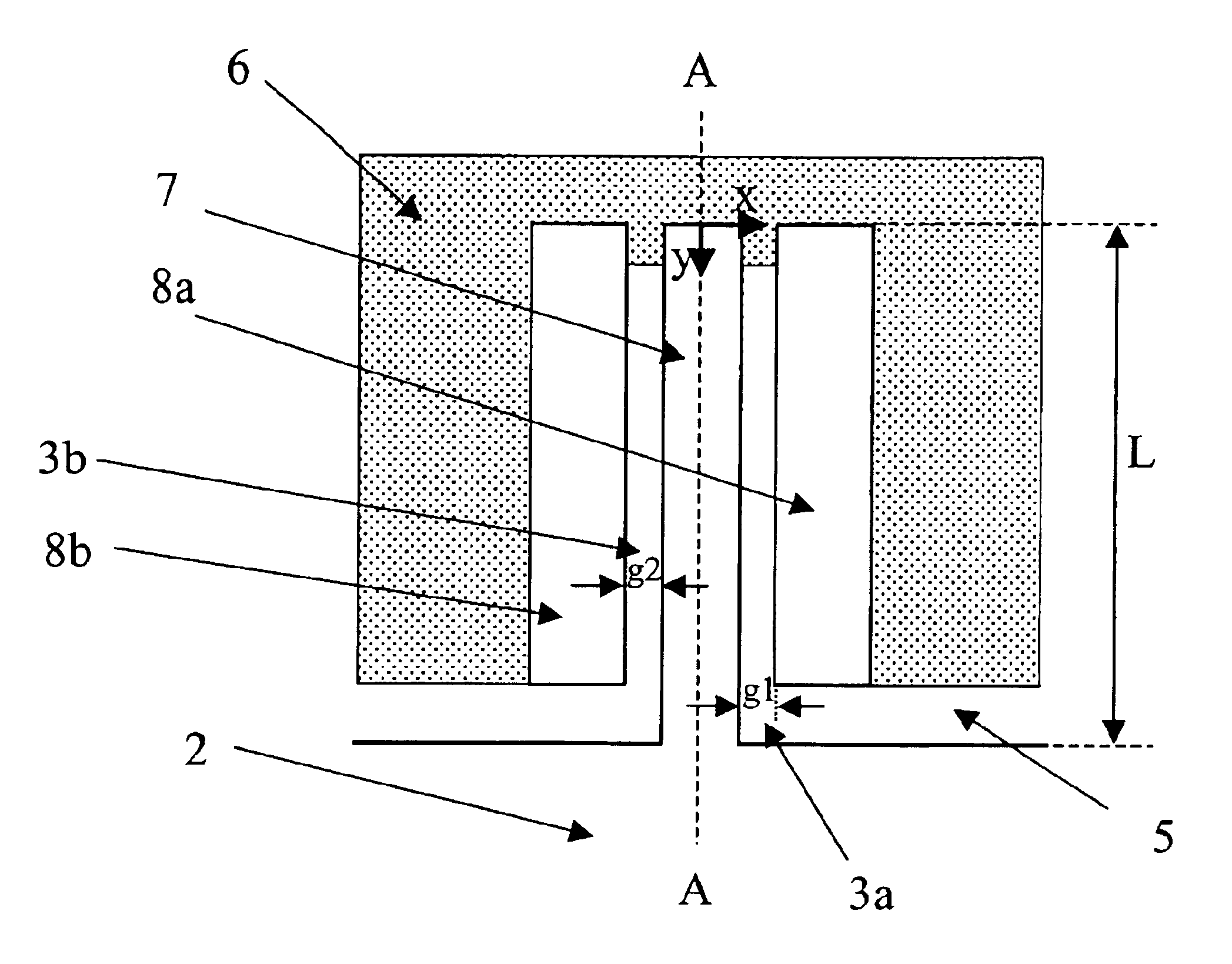
[0032]FIG. 2A shows a top plan view of one embodiment of a torsional micro-mirror system 25. FIG. 2B is a top plan view showing an enlargement of both the flexure 7 and the stationary structure 8, which are encircled in FIG. 2A. FIG. 2C shows a cross-sectional view of FIG. 2A taken along the centerline A.

[0033]In this embodiment, a vertical electrostatic actuator 33 includes, among other things, stationary structures 8a-b attached to a substrate 20 as shown in FIG. 2B and acting as stationary electrodes. The flexure 7, rotating element 2 and electrodes 8a-b comprise two conducting or semiconducting layers a and b separated by an insulating layer 16 as shown in FIG. 2C.

[0034]The flexure 7 acts as a mobile electrode. The rotating element 2 is suspended over a cavity 5 and connected to a base 6 by tors...


PUM


Abstract

A vertical electrostatic actuator is based on a layered structure consisting of two conducting or semiconducting layers separated by an insulating layer and/or layered structure consisting of p-type and n-type layers separated by a pn-junction. The number of conducting layers, p-type layers and/or n-type layers can be more than two as long as each two adjacent layers are separated by an insulating layer or a pn-junction. The mobile electrode of the actuator can be formed along a flexure in a micro-mechanical system. Two stationary electrodes are located on either side of the mobile electrode. The layered structure of the electrodes increases the torque on the flexure and thus improves the performance of the actuator. Fabrication methods for the electrostatic actuator and micro-mechanical systems employing the same are disclosed.

Description

CROSS-REFERENCE TO RELATED APPLICATION[0001]This application is a continuation of application Ser. No. 10 / 315,366, filed Dec. 10, 2002 now U.S. Pat. No. 6,757,092, which claims the benefit of prior Provisional Application Nos. 60 / 338,917 filed Dec. 10, 2001 and 60 / 380,250 filed on May 13, 2002. Each of these applications is fully incorporated by reference herein as though set forth in full.TECHNICAL FIELD[0002]The present invention generally relates to micro-electro mechanical systems (MEMS), and more particularly, to electrostatic actuators and micro-mechanical systems employing the same and methods for fabricating and operating such devices.BACKGROUND[0003]Micro-Electro-Mechanical Systems (MEMS) technology has been used increasingly in the development of many micro devices such as optical switches. MEMS technology utilizes lithographic mass fabrication processes used by the semiconductor industry in manufacturing integrated circuits (ICs). MEMS based switches consist of arrays of ...

Claims


Application Information

Patent Timeline
IPC IPC(8): H02N1/00
CPCH02N1/008H02N1/002
Inventor ABU-AGEEL, NAYEF M.
Owner ABU AGEEL NAYEF M
Why Eureka
Try Eureka