Switching power supply unit

a technology of switching power supply and power supply unit, which is applied in the direction of electric variable regulation, process and machine control, instruments, etc., can solve the problems of reducing the conversion efficiency of the whole switching power supply unit, power loss, and damage to the synchronous rectifying switch element, so as to prevent the generation of through current

Inactive Publication Date: 2005-05-03
TDK CORPARATION
View PDF25 Cites 176 Cited by
  • Summary
  • Abstract
  • Description
  • Claims
  • Application Information

AI Technical Summary

Benefits of technology

[0035]It is therefore an object of the invention to provide a switching power supply unit adapted to effectively prevent the generation of through currents.
[0036]Another object of the invention is to provide a switching power supply unit capable of substantially improving the reliability of a self-drive type secondary rectifier circuit and also forming a highly efficient power supply at low cost.

Problems solved by technology

The through currents result in power loss and the problem is that the lowering of conversion efficiency is caused to the whole switching power supply unit.
In case where the commutation period is longer than delay in the operation of the synchronous rectifying switch element (turn on / off period), through current flows as the synchronous rectifying switch elements are simultaneously turned on and the synchronous rectifying switch elements may be damaged when the worst comes to the worst.
However, power loss may increase caused by the increase of the interval that the synchronous rectifying switch element cannot be turned on, and further, there may be brought about a bad influence resulting from an increase in loss because of the leakage inductance and spike noise.
However, the problem in this case is that a switching power supply unit tends to become large-sized accompanied with an increase in cost as the number of parts increases.
In case where the user is allowed to switch the output voltage Vo between 3.3V and 1.5V, a step-down range to be covered by the buck converter circuit 3 as the first stage converter grows larger, and the load of the buck converter circuit 3 is heavy when lower voltage (e.g., 1.5V) is required as the output voltage Vo, and the problem is that loss tends to increase.
In this case, however, the stability of the output voltage Vo may be ruined because a plurality of converters operate to stabilize the output voltage Vo.
In order to prevent the stability of the output voltage Vo from being ruined, the converter-to-converter operation needs to be properly regulated, which results in complicating the control operation.
Consequently, as the conducting period of the rectifier transistors constituting the rectifier circuit becomes shortened, current is allowed to flow into the body diodes over a long period of time.

Method used


Image

  • Switching power supply unit
  • Switching power supply unit
  • Switching power supply unit

Examples


embodiment 1

[0080](Embodiment 1)

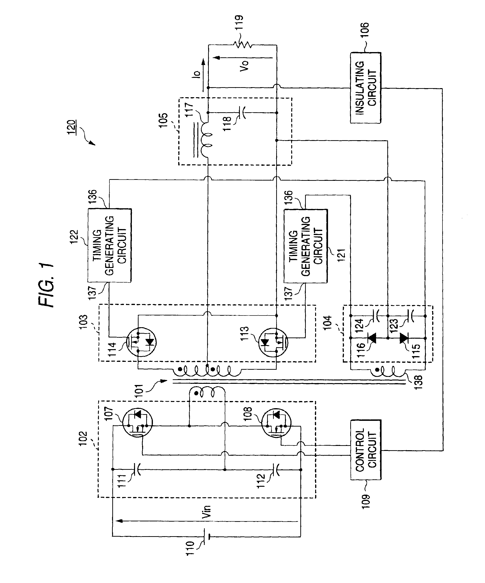
[0081]FIG. 1 is a circuit diagram of a switching power supply unit 120 as the first embodiment of the invention.

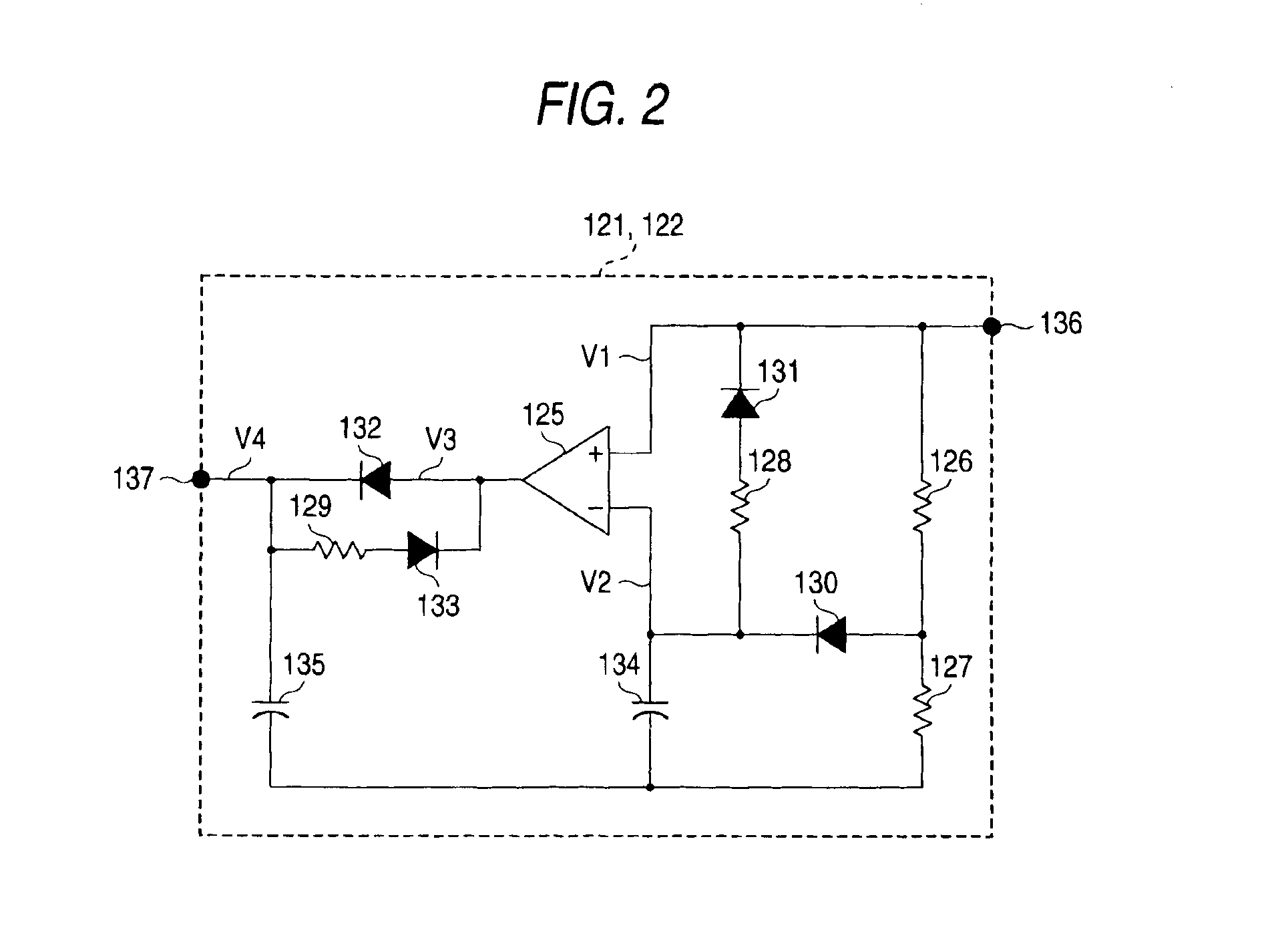
[0082]As shown in FIG. 1, the switching power supply unit 120 according to this embodiment of the invention is a synchronous rectifying switching power supply unit of a so-called half-bridge type like a typical conventional switching power supply unit. However, the switching power supply unit 120 according to this embodiment of the invention is different in that: a first timing generating circuit 121 is inserted in between a rectifier-transistor driving circuit 104 and the gate of a first rectifier transistor 113, and a second timing generating circuit 122 is inserted in between the rectifier-transistor driving circuit 104 and the gate of a second rectifier transistor 114; and that a first auxiliary capacitor 123 is connected between both ends of a first diode 115, and a second auxiliary capacitor 124 is connected between both ends of a second diode 116...

embodiment 2

[0110](Embodiment 2)

[0111]The second embodiment of the invention will now be described in detail with reference to the drawings, wherein like reference characters are given to like members in the drawings and the repeated description thereof is omitted. This embodiment of the invention is a mode specifically useful for implementing the invention and the invention is not limited to the embodiment described herein.

[0112]FIG. 8 is a circuit diagram of a switching power supply unit; FIG. 9 is a timing chart showing the voltage / current waveform of each portion in the switching power supply unit of FIG. 8 when the sum of a dead time period and commutation period of a transformer leakage is equal to switching delay time of a synchronous rectifying element; FIG. 10 is a timing chart showing the voltage / current waveform of each portion when the commutation period of the transformer leakage is shorter than switching delay time of the synchronous rectifying element in the switching power suppl...

embodiment 3

[0152](Embodiment 3)

[0153]A detailed description will now be given of the third embodiment of the invention by reference to the accompanying drawings.

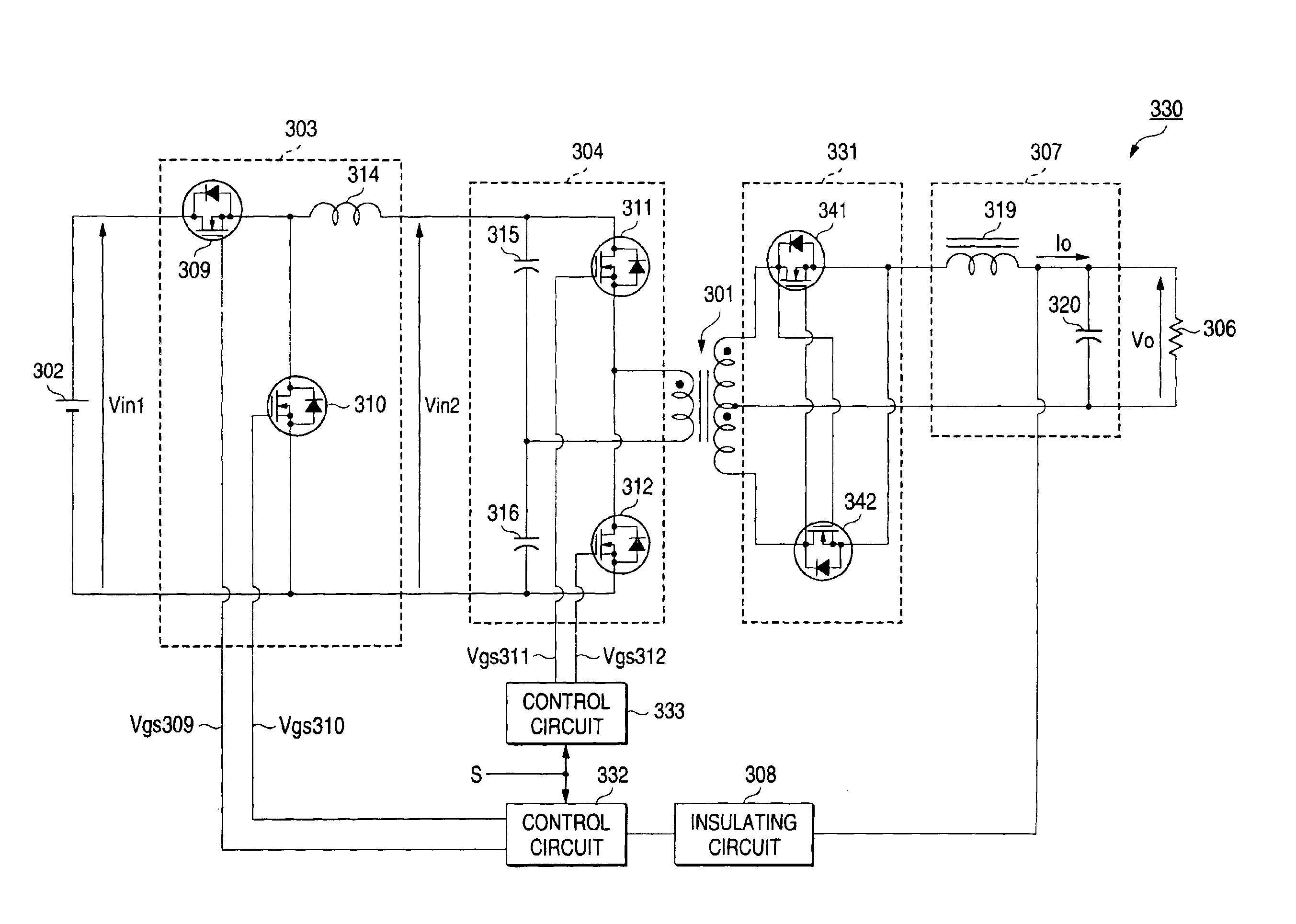
[0154]FIG. 13 is a circuit diagram of a switching power supply unit 330 according to the third embodiment of the invention.

[0155]As shown in FIG. 13, a switching power supply unit 330 according to this embodiment of the invention is what employs a primary circuit including a buck converter circuit and a half-bridge circuit that are connected in series like a conventional switching power supply unit. The switching power supply unit 330 is different from the conventional (third related art) switching power supply unit in that the rectifier circuit 55 provided in the conventional switching power supply unit is replaced with a rectifier circuit 331 and that control circuits 332 and 333 are provided in place of the control circuit 63 provided in the conventional switching power supply unit. As to the rest, because the switching power supply...


PUM


Abstract

A switching power supply unit of the present invention a timing generating circuit (121) which receives a first control signal formed by a rectifier-transistor driving circuit (104), forms a second control signal based on the first control signal, and supplies the second control signal to a control electrode of the rectifier transistor (113).The first control signal is synchronized with the switching operation of a half-bridge circuit (102), and the second control signal exceeds a threshold voltage of a rectifier transistor (113) at a timing substantially equal to the timing that one edge of the first control signal is generated and falls below the threshold voltage of the rectifier transistor (113) at a timing earlier by predetermined time than the timing that the other edge of the first control signal is generated.

Description

[0001]This is a Divisional of application Ser. No. 10,152,788, filed May 23, 2002, now U.S. Pat. No. 6,650,552.BACKGROUND OF THE INVENTION[0002]The present invention relates to a switching power supply unit, and more particularly to a synchronous rectifying switching power supply unit, a switching power supply unit having a half-bridge circuit, and a switching power supply unit using a plurality of converters connected in series.[0003](Related Art 1)[0004]Conventionally, DC / DC converters are known as a switching power supply unit. A typical DC / DC converter converts an alternating current input to direct current once by using a switching circuit, then transforms (boosting or lowering) the voltage by using a transformer, and further converts the direct current to alternating current by using an output circuit, whereby alternating current output having voltage different from the input voltage can be obtained.[0005]In some cases, switching elements such as transistors are employed in an...

Claims


Application Information

Patent Timeline
Patent Type & Authority Patents(United States)
IPC IPC(8): H02M3/335H02M3/24
CPCH02M3/33592Y02B70/1475Y02B70/10
Inventor TAKAGI, MASAKAZUYAMAMOTO, JUNICHISHIMIZU, KATSUHIKOZAITSU, TOSHIYUKI
Owner TDK CORPARATION
Why Eureka
Try Eureka