Personal sound masking system

a sound masking and personal technology, applied in the field of personal sound masking systems, can solve the problems of limited acoustic measures that can be employed to reduce the level of the resulting speech that is transmitted, prohibitive costs, and few smaller offices that use such systems, and achieve the effect of simple installation and easy modification

Inactive Publication Date: 2005-05-03
CAMBRIDGE SOUND MANAGEMENT
View PDF36 Cites 31 Cited by
  • Summary
  • Abstract
  • Description
  • Claims
  • Application Information

AI Technical Summary

Benefits of technology

[0012]In accordance with the present invention, a sound masking system is disclosed that provides sound masking over an multi-occupant area such

Problems solved by technology

Limited acoustical measures can be employed to reduce the level of the resulting speech that is transmitted.
However, few smaller offices use such systems due to prohibitive costs.
If it has any readily identifiable or unnatural characteristics such as “rumble,”“hiss,” or tones, or if it exhibits obvious temporal variations of any type, it readily becomes a source of annoyance itself.
However, if the sound has a sufficiently neutral, unobtrusive spectrum of the right shape, it can be raised, without becoming objectionable, to a sound level or volume nearly equal to that of the intruding speech itself, effectively masking it.
Although a distributed, ceiling mounted sound masking system has numerous advantages, such a system has significant disadvantages that interfere with the effectiveness of the system at the level of the individual office worker.
For example, mechanical system ducts and other physical obstructions, as well as acoustical variations in the above-ceiling plenum and ceiling components such as vented light fixtures and air return grilles, pose significant challenges to the designer in achieving adequately uniform spectral quality.
In many installations, cavity resonances in the plenum occur and cannot be completely ameliorated by equalization or other techniques.
As a consequence, the acoustical spectrum obtainable at any one office worker location may be substantially compromised compared to the ideal spectrum desirable at his or her particular location.
This non-ideal spectrum and spatial variation throughout the office places an effective upper limit on the effectiveness of the masking system.
The volume of sound needed may be relatively low if the intervening office construction, such as airtight full height walls, provides high NR, but it must be relatively high in level if the construction NR is compromised by partial-height intervening partitions or acousti

Method used


Image

  • Personal sound masking system
  • Personal sound masking system
  • Personal sound masking system

Examples


Embodiment Construction

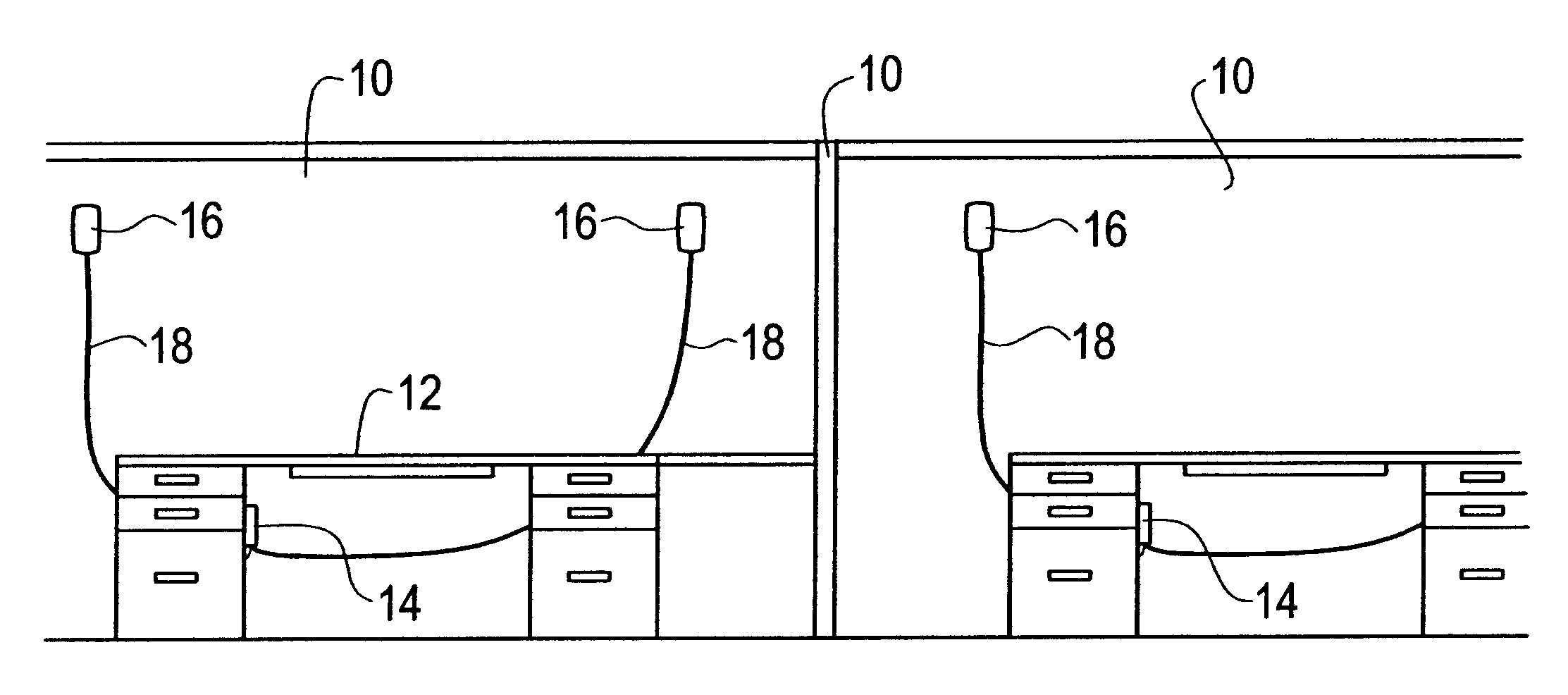
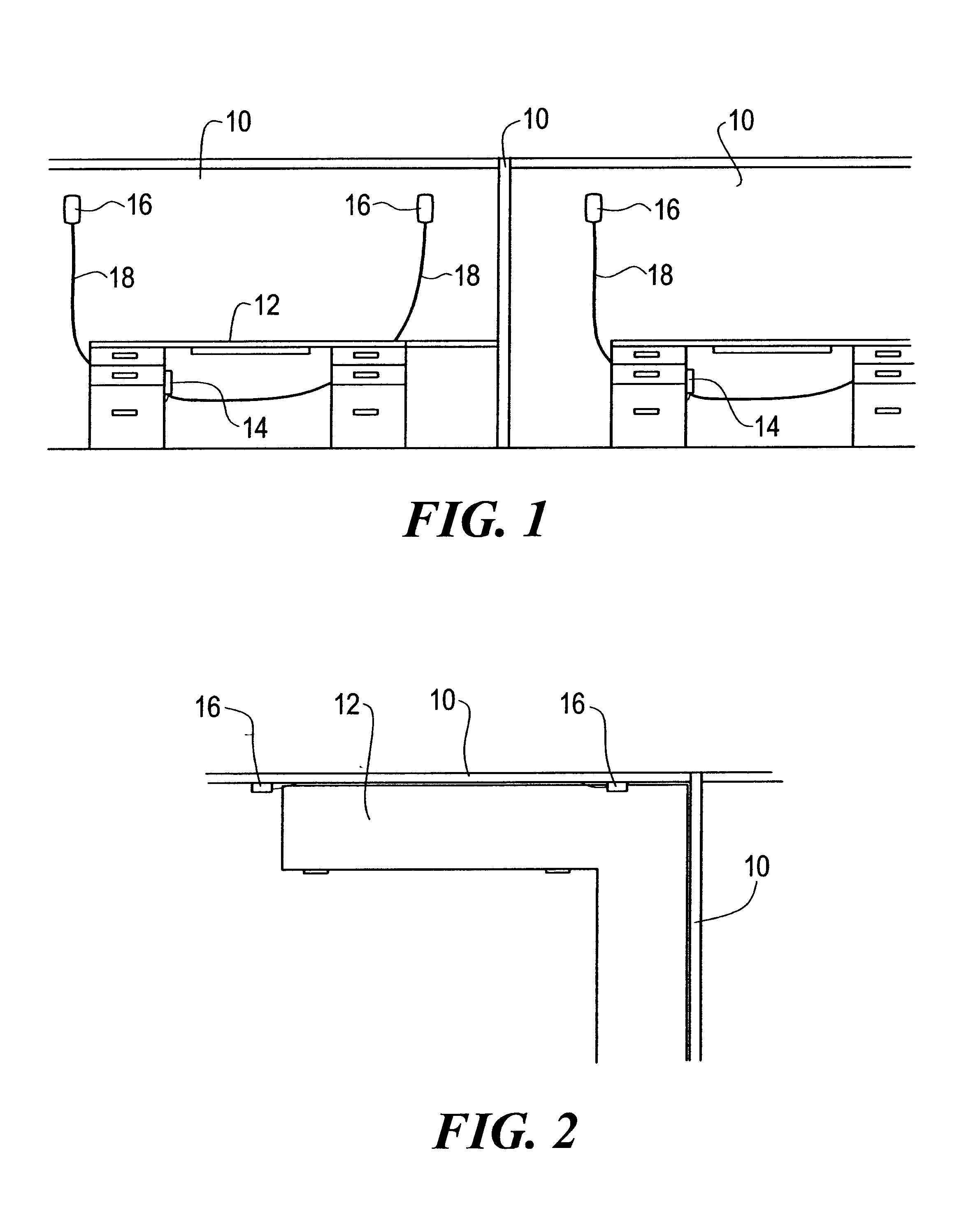
[0027]FIGS. 1 and 2 show a typical open-plan office, often referred to as a “cubicle.” The offices are separated by partitions 10 whose height is typically in the range of 4.5 to 7 feet, but may be so low or so acoustically transparent that no acoustical blocking is achieved. The office occupant may sit at a desk 12 or other station. A sound masking system includes a control module 14 mounted on an inside inner panel of the desk 12, using for example mating hook-and-pile tabs secured to the desk 12 and control module 14 respectively. The control module 14 is connected to A and B channel loudspeakers 16 via telephone-type multi-conductor cables 18. The loudspeakers 16 are secured to a partition 10 using suitable means, examples of which are described below.

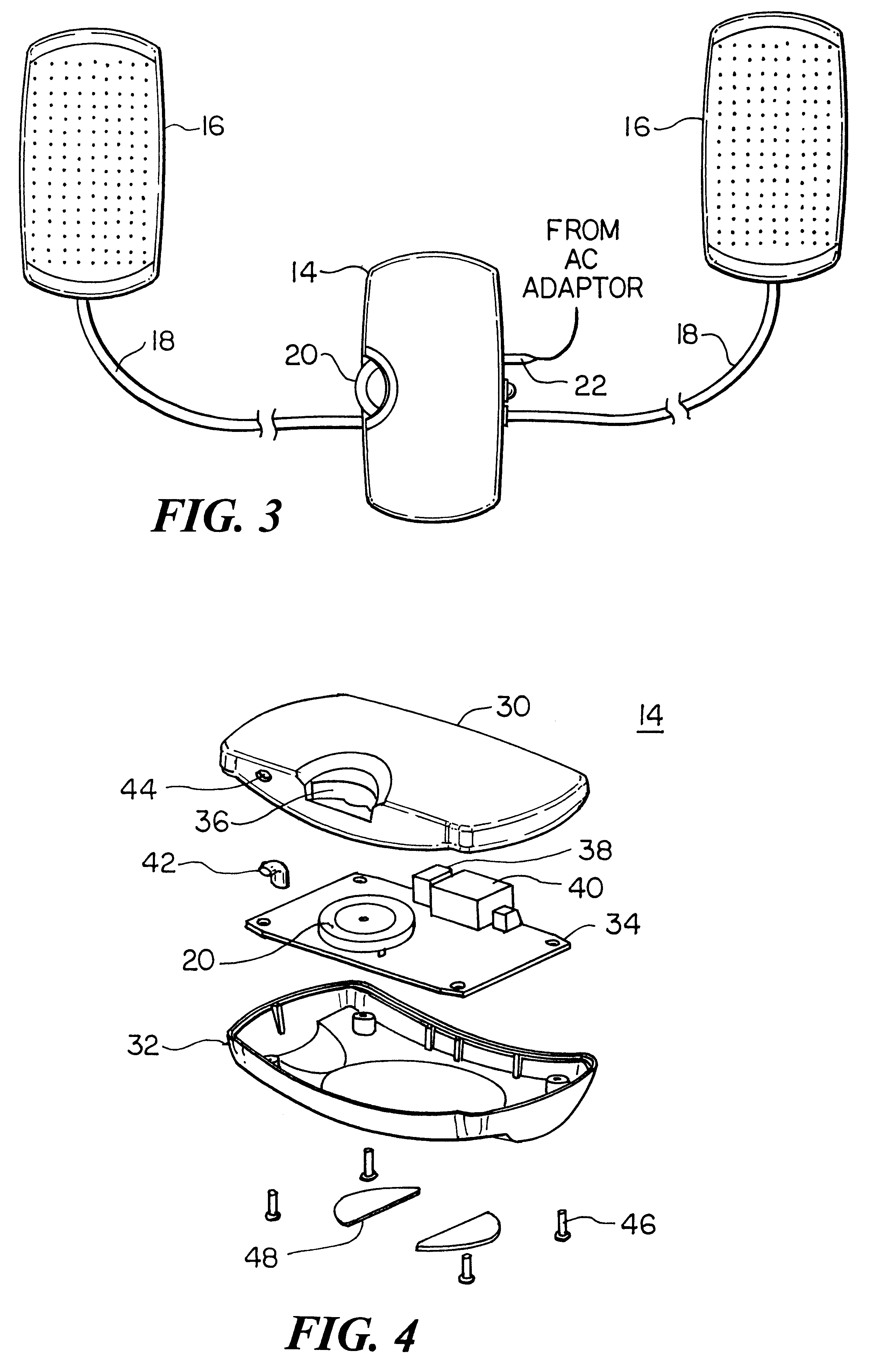
[0028]FIG. 3 shows the elements of the personal sound masking system. The control module 14 has a user-accessible volume control 20. The loudspeaker cables 18 connect to the control module 14 using telephone-type modular plugs and ...


PUM


Abstract

A sound masking system for a multi-occupant work area includes a masking signal generator generating incoherent masking sound signals loudspeaker modules interconnected in a daisy-chain fashion, with each loudspeaker module receiving the masking sound signals on input connections and transmitting them to a successive loudspeaker module on output connections. The connections on which the masking sound signals appear in each loudspeaker are shifted by the inter-loudspeaker connections, such that successive loudspeakers automatically emit different masking sound signals for improved diffuseness in the overall masking sound in the work area. Each loudspeaker module has one jack having the input connections and another jack having the output connections, and each jack receives a detachable cable such as telephone cable to connect adjacent loudspeaker modules. The masking sound signals are shifted by a cross connection network between the two jacks in each loudspeaker module.

Description

CROSS REFERENCE TO RELATED APPLICATIONS[0001]This application is a continuation in part of U.S. application Ser. No. 09 / 266,186, filed Mar. 10, 1999 and issued on Feb. 13, 2001 as U.S. Pat. No. 6,188,771, which claims priority under 35 U.S.C. §119 (e) of U.S. Provisional Application No. 60 / 077,535, Filed Mar. 11, 1998, entitled “Personal Sound Masking System”, the disclosures of both of these applications being hereby incorporated by reference herein.STATEMENT REGARDING FEDERALLY SPONSORED RESEARCH OR DEVELOPMENT[0002]Not ApplicableBACKGROUND OF THE INVENTION[0003]It is well known that freedom from distraction is an important consideration for workers' satisfaction with their office environment. In a conventional enclosed office with full height partitions and doors, any speech sound intruding from outside the office is attenuated or inhibited by the noise reduction (NR) qualities of the wall and ceiling construction. Residual speech sound actually entering the office is normally ma...

Claims


Application Information

Patent Timeline
IPC IPC(8): G10K11/00G10K11/175H04R5/00H04R5/033
CPCG10K11/175H04R5/033H04R1/1083H04R1/1041H04K3/825H04K2203/12H04K3/84H04K2203/34G10K11/1754
Inventor HORRALL, THOMAS R.
Owner CAMBRIDGE SOUND MANAGEMENT
Why Eureka
Try Eureka