Gas turbine combustor
- Summary
- Abstract
- Description
- Claims
- Application Information
AI Technical Summary
Benefits of technology
Problems solved by technology
Method used
Image
Examples
Embodiment Construction
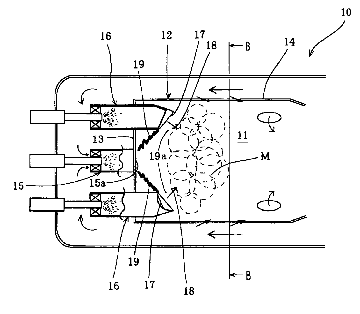
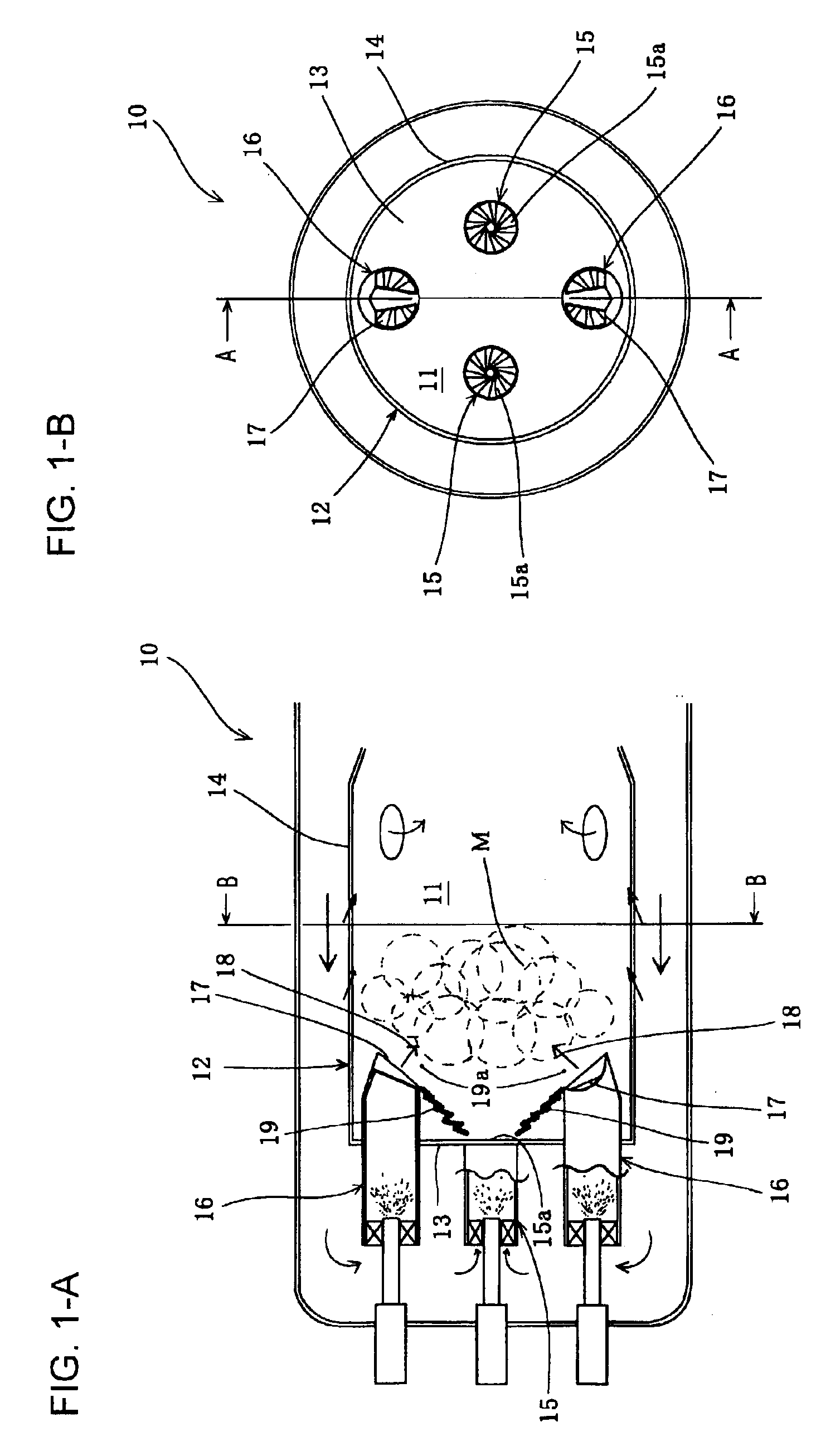
[0053]Embodiments of the gas turbine combustor of the present invention will be described below with reference to the attached figures. FIG. 1 is a diagram which shows an embodiment in which the gas turbine combustor of the present invention is used as a can type combustor employed in a small liquid fueled gas turbine used for power generation. FIG. 1-A is a longitudinal section along the plane A—A in FIG. 1-B, and FIG. 1-B is a cross section along the plane B—B in FIG. 1-A.
[0054]In the gas turbine combustor 10 (hereafter abbreviated to “combustor 10”) shown in FIG. 1, the combustor liner 12, which forms a can combustion chamber 11, is constructed from a liner dome wall part 13, which constitutes the end wall on the upstream side, and a tubular wall part 14 which extends downstream from the liner dome wall part 13. In the liner dome wall part 13, two burners 15 which have the same configuration are attached in positions that are symmetrical in the direction of diameter with respect ...
PUM
 Abstract
Description
Claims
Application Information
 - R&D
- Intellectual Property
- Life Sciences
- Materials
- Tech Scout
- Unparalleled Data Quality
- Higher Quality Content
- 60% Fewer Hallucinations
Browse by: Latest US Patents, China's latest patents, Technical Efficacy Thesaurus, Application Domain, Technology Topic, Popular Technical Reports.
© 2025 PatSnap. All rights reserved.Legal|Privacy policy|Modern Slavery Act Transparency Statement|Sitemap|About US| Contact US: help@patsnap.com


