Full mold casting process and device for a differential case with cast-in bolt holes

a technology of differential case and mold casting process, which is applied in the direction of foundry molds, metal-working equipment, foundry patterns, etc., can solve the problems of only possible mold division, mold joint defects, and not all types of models can be molded

Inactive Publication Date: 2005-05-10
DANA AUTOMOTIVE SYST GRP LLC
View PDF9 Cites 7 Cited by
  • Summary
  • Abstract
  • Description
  • Claims
  • Application Information

AI Technical Summary

Benefits of technology

[0018]In accordance with the objects described above, the invention is a method for making a differential case metal casting or similar article and the resulting product. The method comprises the following steps: (a) providing an in situ destroyable foam pattern to form an integral one-piece differential case casting of a desired shape. The pattern has a hollow body including a substantially annular central wall section and axially spaced side wall sections adjacent to opposite ends of the central wall section forming an internal cavity within the hollow body of the foam pattern. The

Problems solved by technology

However, this division of the molds is only possible within certain dimensional tolerances, and as a consequence, defects may occur within the mold joint due to offset burrs, sand washouts, metal penetrating into the sand mold, charred portions of sand, and the like.
It has been found, however, that not all types of models can be molded in this manner and it is especially difficult to satisfactorily embed moldings with dome-shaped cavities, such as one-piece differential case members and similar shapes, in the sand because the sand does not rise to fill these cavities.
It is, therefore, a disadvantage of this known lost foam casting process that such molding

Method used


Image

  • Full mold casting process and device for a differential case with cast-in bolt holes
  • Full mold casting process and device for a differential case with cast-in bolt holes
  • Full mold casting process and device for a differential case with cast-in bolt holes

Examples


Embodiment Construction

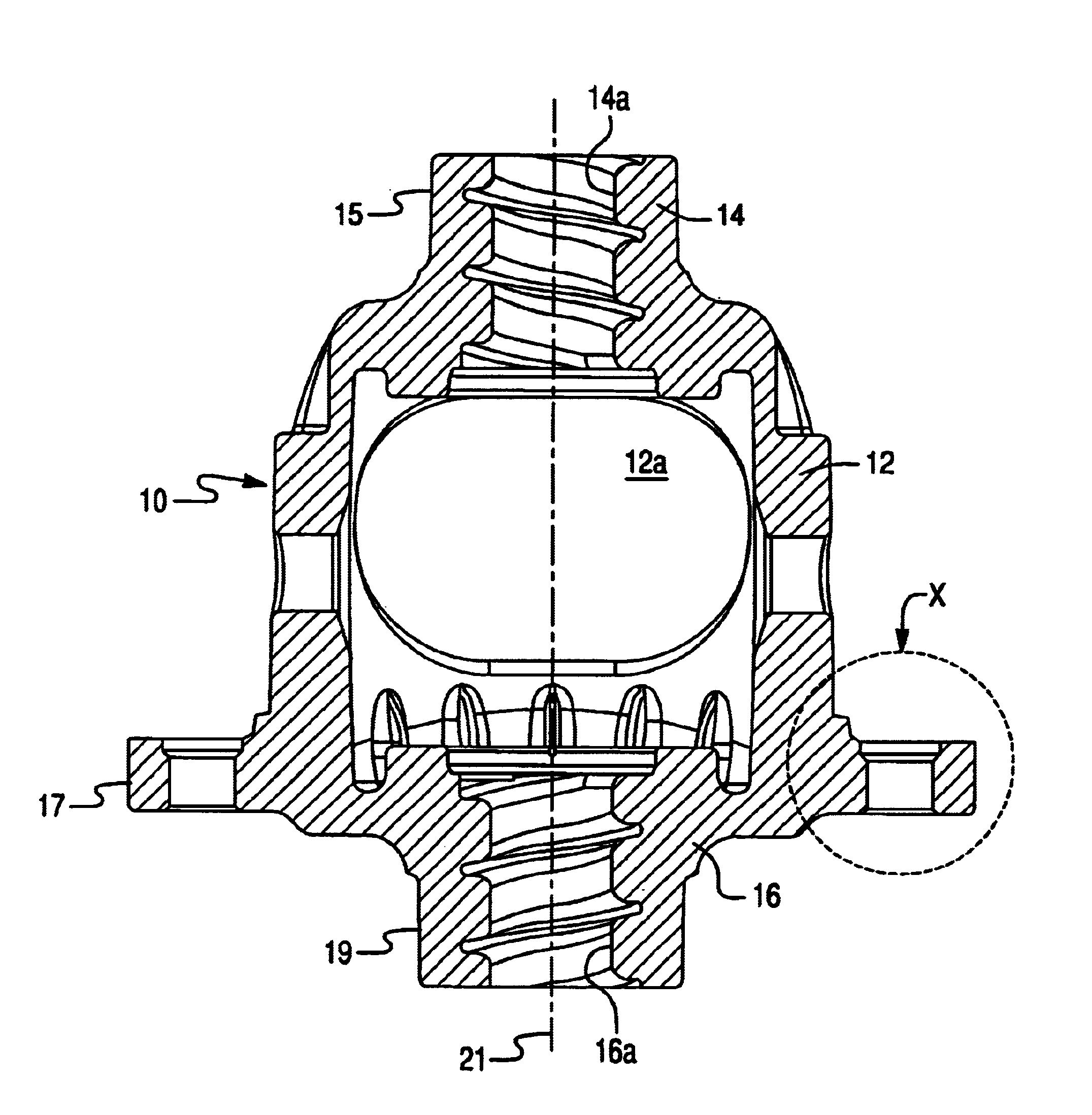
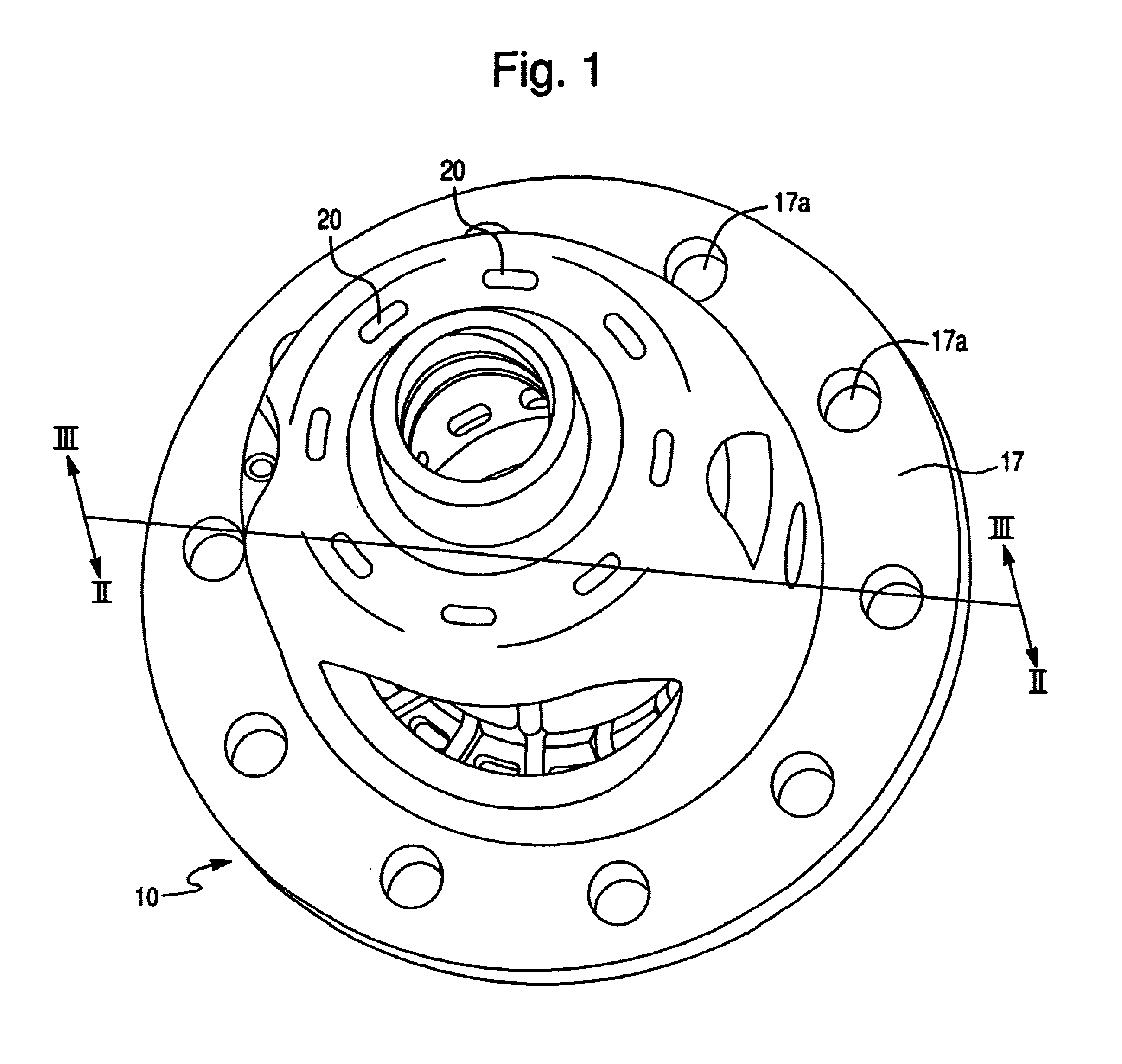
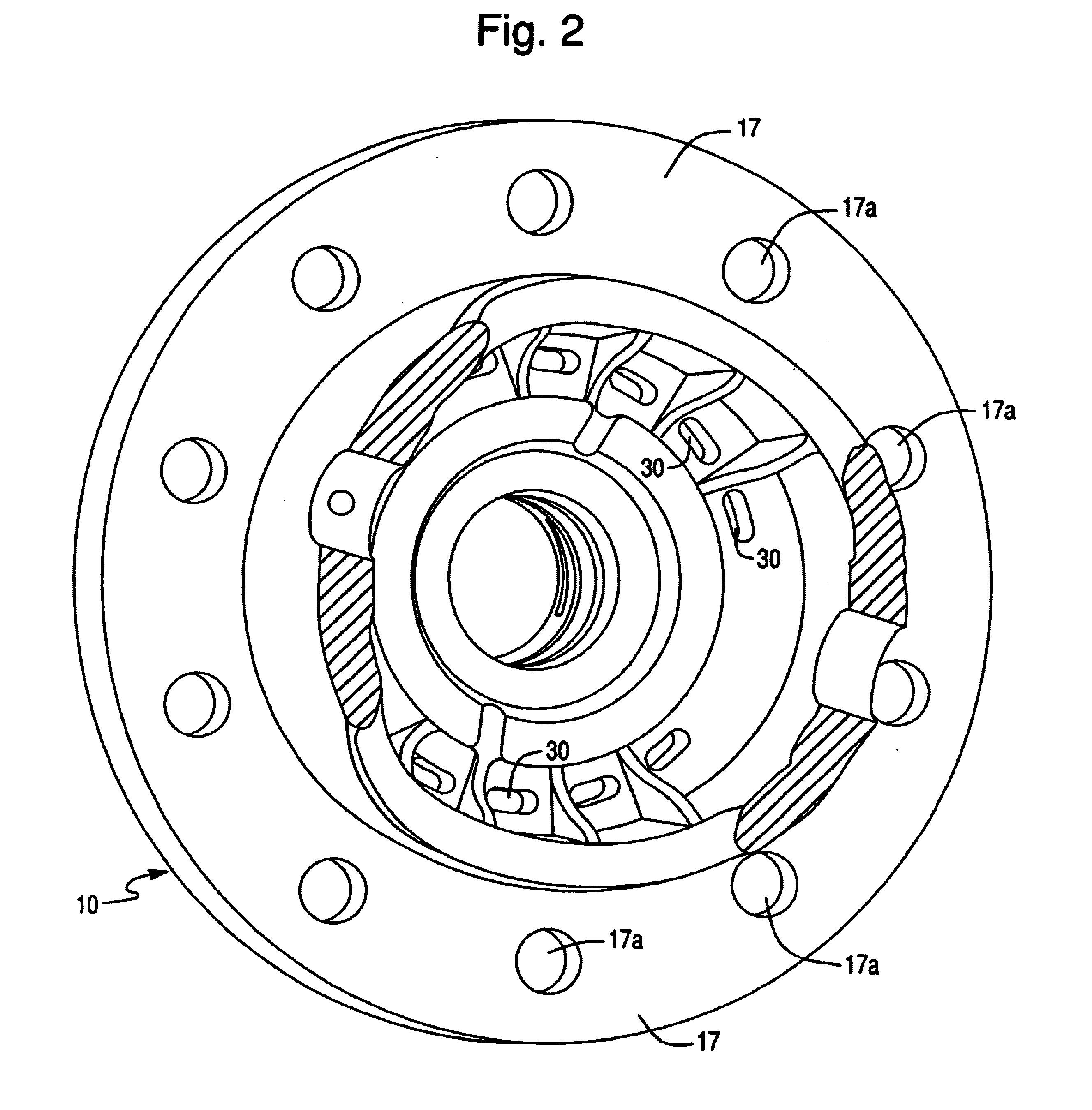
[0030]With reference to FIG. 1, the invention is a method for making a differential case metal casting. The method comprises the step of providing an in situ destroyable foam pattern 10 as shown in FIGS. 1-10 to form an integral one-piece differential case casting of the desired shape identical also to the product shown in FIGS. 1-10. The pattern has a hollow body including a substantially annular central wall section 12 and axially spaced side wall sections 14, 16 adjacent to opposite ends of the central wall section 12 forming an internal cavity within the hollow body of the foam pattern. See FIG. 4. The pattern (and, thus, the differential case) includes two sets of pass-through openings 20, 30 on the side wall sections 14, 16 of the hollow body of the pattern adjacent to the respective opposite end of the central wall section 12.

[0031]In the subsequent step of the method, the mold pattern is embedded in unbonded sand so that the unbonded sand is at least partially introduced int...


PUM


Abstract

A peripheral flange formed on a differential case for mounting a ring gear and the peripheral flange is provided with a plurality of cast-in bolt holes for bolting up the ring gear to the differential case using the lost foam casting process for making the differential case. A method of making a gear case eliminates the process of machining of the bolt holes in the differential case casting, thus reducing cost of manufacturing the differential case.

Description

BACKGROUND OF THE INVENTION[0001]1. Field of the Invention[0002]The instant invention relates to a full mold casting process for a differential case member with cast-in bolt holes in which a complete positive model, made of a thermally decomposable material, is placed into a molding box filled with sand. The sand may be compacted by any suitable method such as shaking, and the casting metal is poured on the thermally decomposable model. The model is decomposed by the casting heat.[0003]2. Description of Related Art[0004]To produce castings, molds consisting of two halves are generally used.[0005]However, this division of the molds is only possible within certain dimensional tolerances, and as a consequence, defects may occur within the mold joint due to offset burrs, sand washouts, metal penetrating into the sand mold, charred portions of sand, and the like. All these defects appear on the casting and must be eliminated by grinding, stripping, knocking, sawing, or the like.[0006]Mor...

Claims


Application Information

Patent Timeline
IPC IPC(8): B22C9/02B22C9/04
CPCB22C9/046
Inventor JENSEN, WILLIAM GLENCATALANO, MICHAEL J
Owner DANA AUTOMOTIVE SYST GRP LLC
Why Eureka
Try Eureka