Capillary tube heat pipe and temperature controlling apparatus

a technology of capillary tubes and heat pipes, applied in the direction of insulated conductors, cables, semiconductor/solid-state device details, etc., can solve the problems of not being able to describe, achieve improved heat transportable distance, prevent the damage of the peltier element, and improve heat transportable capacity

Inactive Publication Date: 2005-05-10
MIZUTANI ELECTRIC IND
View PDF15 Cites 16 Cited by
  • Summary
  • Abstract
  • Description
  • Claims
  • Application Information

AI Technical Summary

Benefits of technology

[0021]In the present invention, it is preferable that said meandering turn portion is heated or cooled at one turn end side and is cooled or heated at another turn end side so as to cause a working fluid in said meandering turn portion to be evaporated and condensed, thereby increasing a flow force of the working fluid in said meandering turn portion.
[0022]By increasing a flow force of the working fluid in the heat receiving portion and / or the heat radiating portion, the original flow force of the working fluid between the heat receiving portion and the heat radiating portion associated with evaporation and condensation of the working fluid is increased, thereby increasing the flow force of the working fluid in the whole capillary tube heat pipe (called as booster effect). Hereby, a considerable quantity of the working fluid can be flowed for a long distance so that a heat transporting capacity can be increased and a heat transportable distance can be lengthened.
[0024]By intervening the high heat conductive member, a heat conductivity between the heat receiving portion and / or the heat radiating portion of the heat pipe and an object to be heated or an object to be cooled (a heat receiving portion and a heat radiating portion) becomes larger (since the contact area becomes larger), so that the heat can be effectively transferred to the portion from which heat to be transferred is generated (an object to be cooled in the case of hot heat, an object to be heated in the case of cold heat) to the portion from which the heat is radiated (an object to be heated in the case of hot heat, an object to be cooled in the case of cold heat). And, by embedding the capillary into the groove of the boss, the heat conductivity between the capillary and the boss becomes larger. Also, the capillary does not deform even if a mechanical compressive stress is applied when the boss is mounted to the object to be heated or the object to be cooled.
[0028]Hereby, the heat transportable capacity and the heat transportable distance are improved as compared with the case in which said meandering turn portion is not cooled or heated at both turn end sides. Here, the medium for radiating heat produced by a heat generating element of said heat generating device is described hereinafter referring to the case in which a Peltier element is used for the heat generating element. The Peltier element has a plate shape, and is provided with a cold heat generating face at one surface thereof and a heat radiating face at the opposite surface. In this case, one surface which is contacted with the heat receiving portion of the heat pipe becomes a thermal working surface (for instance, a cold heat generating face), and the opposite surface produces a counter thermal working (for instance, a hot heat radiating). When hot heat is radiated from the opposite surface, it is necessary to cool the opposite surface by a medium, such as air, in order to prevent the Peltier element from being damaged by excessive heating. In the present invention, the medium is intentionally used for an assistant heat source in order to increase the booster effect in the meandering turn portion.

Problems solved by technology

However, it does not describe the case of a closed loop type heat pipe having one pair of going and returning passages.

Method used


Image

  • Capillary tube heat pipe and temperature controlling apparatus
  • Capillary tube heat pipe and temperature controlling apparatus
  • Capillary tube heat pipe and temperature controlling apparatus

Examples


first embodiment

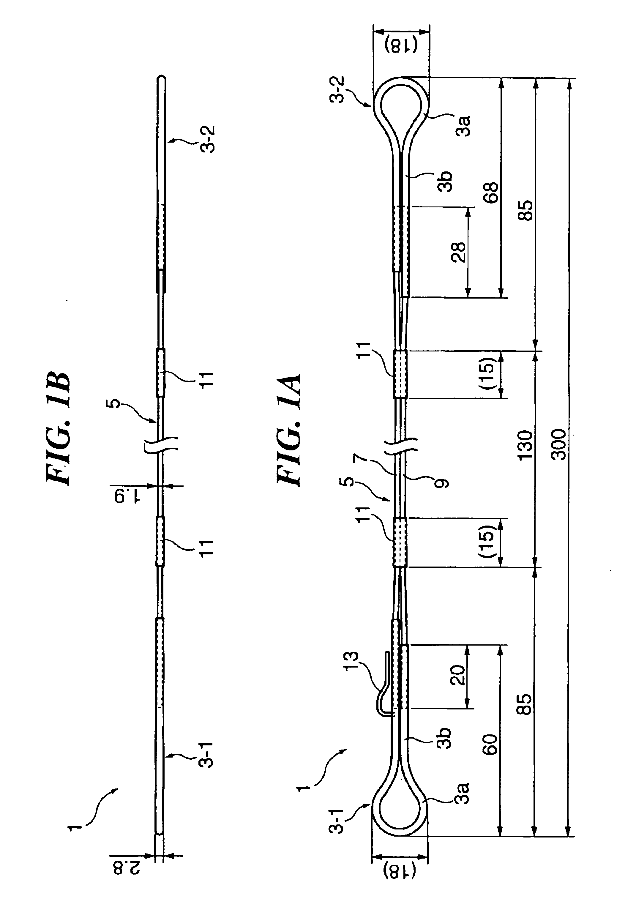
[0041]FIG. 1 is a drawing showing a structure of a capillary tube heat pipe according to the present invention, FIG. 1(A) is a plan view and FIG. 1(B) is a side view. The sizes to be hereinafter described are examples.

[0042]This capillary tube heat pipe 1 is provided with two turn portions (a heat receiving portion and a heat radiating portion) 3-1 and 3-2 at the both ends thereof and a straight portion (a heat transfer portion) 5 extending between the both turn portions 3, and has a closed loop structure in which both terminals of a single pipe are communicated. The both turn portions 3-1 and 3-2 are made of high heat conductive material, such as copper.

[0043]Each of the turn portions 3 is made from a pipe having a length of 140 mm, an outer diameter of 2.8 mm and an inner diameter of 2.1 mm. The pipe is bent into a substantially circle shaped loop 3a having a diameter of 18 mm at an approximate center thereof. A proximal part 3b of the loop 3a is made from the straightly and adjac...

second embodiment

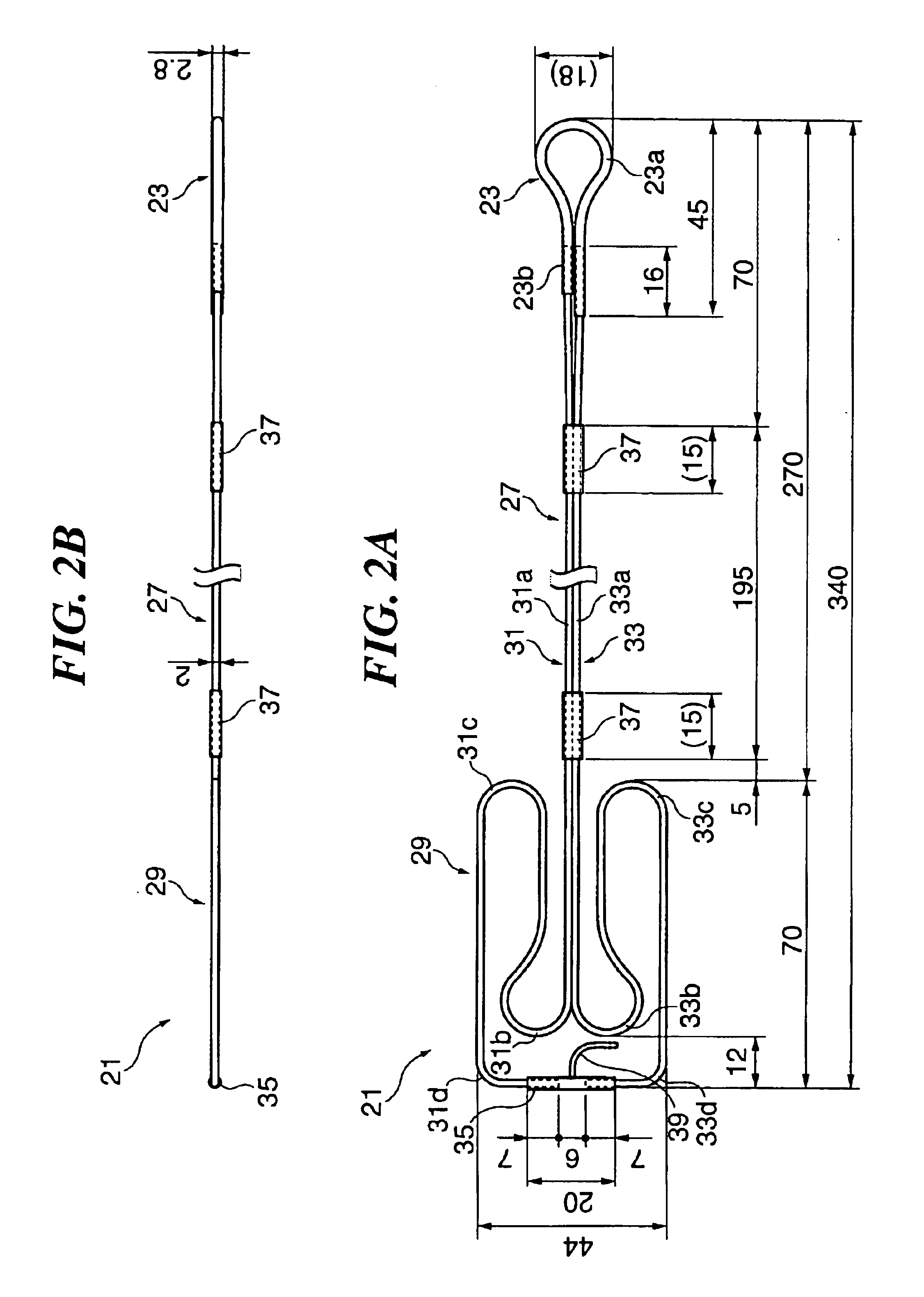
[0048]FIG. 2 is a drawing showing a structure of a capillary tube heat pipe according to the present invention, FIG. 2(A) is a plan view and FIG. 2(B) is a side view.

[0049]The capillary tube heat pipe 21 has a substantially same structure as that of the heat pipe 1 shown in FIG. 1 except for a structure of one of the turn portions.

[0050]The capillary tube heat pipe 21 is provided with one turn portion 23 in the right end, a meandering turn portion 29 in the left end, and a straight portion 27 which connects both turn portions, and has a closed loop structure in which both terminals of a single pipe are communicated.

[0051]The one turn portion 23 is made from a pipe having a length of 100 mm, an outer diameter of 2.8 mm and an inner diameter of 2.1 mm. The pipe is bent into a substantially circle shaped loop 23a having a diameter of 18 mm at an approximate center thereof. A proximal part 23b of the loop 23a is made from the straightly and adjacently extending parts of the pipe. The on...

third embodiment

[0058]FIG. 3 is a drawing showing a structure of a capillary tube heat pipe according to the present invention, FIG. 3(A) is a plan view and FIG. 3(B) is a side view.

[0059]FIG. 4 is a partially cross sectional view showing the capillary tube heat pipe of FIG. 3.

[0060]The capillary tube heat pipe 41 is provided with two bosses (heat conductive members) at the both turn portions 3-1 and 3-2 of the capillary tube heat pipe 1 of FIG. 1. In FIG. 3, each member having a same structure and action as that of the capillary tube heat pipe of FIG. 1 is shown with the same numeral as that of FIG. 1 and explanation is omitted. And, in FIG. 3, the tape 11 is omitted. Also, the heat pipes 1 in FIG. 1 and the heat pipe 21 in FIG. 2 may have no tapes 11 and 37, respectively. The size of each member and part is similar with that of FIG. 1.

[0061]At both turn portions 3-1 and 3-2, bosses (heat conductive members) 45 are mounted, respectively. Each boss 45 is made of high heat conductive material, such ...


PUM


Abstract

A capillary tube heat pipe and the like are provided, in which is applicable for a case that a heat receiving portion is separated apart from a heat radiating portion, and a sufficient space for connecting the both portions does not exist. This capillary tube heat pipe (1) is provided with two turn portions (a heat receiving portion and a heat radiating portion) (3-1) and (3-2) at the both ends thereof and a straight portion (a heat transfer portion) (5) extending between the both turn portions (3), and has a closed loop structure in which both terminals of a single pipe are communicated. Since the heat transfer portion is made from two straight pipes (7) and (9), the straight portion (5) can be small in size.

Description

FIELD OF THE INVENTION[0001]The present invention relates to a heat pipe which radiates heat produced by a heat generating element, such as an electronic component, an internal combustion mechanism (an engine and the like), a driving mechanism of a vacuum pump, and a temperature controlling apparatus using the heat pipe. Particularly, it relates to a capillary tube heat pipe which can be used even when a heat receiving portion is separated apart from a heat radiating portion, and an enough space for connecting the both portions does not exist.BACKGROUND OF THE INVENTION[0002]Radiators have been generally employed for cooling heat generating elements, such as electronic components, internal combustion mechanisms and vacuum pumps. Among several types of the radiators, heat pipe radiators have been well known because of their high heat transfer performance. General heat pipe radiator is constructed mainly from a base plate on which the heat generating element is mounted, and a heat pip...

Claims


Application Information

Patent Timeline
Patent Type & Authority Patents(United States)
IPC IPC(8): F28D15/04F28D15/02H01L23/38H01L23/427H01L23/34
CPCF28D15/0266F28D15/043H01L23/38H01L23/427F28D15/0275H01L2924/0002H01L2924/00
Inventor TAKAMIZAWA, MASAYOSHIKANEKO, TAKASHI
Owner MIZUTANI ELECTRIC IND
Why Eureka
Try Eureka