Phase control in the capillary evaporators

a phase control and capillary evaporator technology, applied in refrigeration and liquidation, lighting and heating apparatus, refrigeration machines, etc., can solve the problems of limited further evolution and application of cpl's, cpl's are disadvantaged during start-up, and its total reliance on subcooled liquid return to maintain stability, etc., to achieve the effect of robust and reliable operation of a lhp

Inactive Publication Date: 2005-05-10
NORTHROP GRUMMAN SYST CORP
View PDF18 Cites 80 Cited by
  • Summary
  • Abstract
  • Description
  • Claims
  • Application Information

AI Technical Summary

Benefits of technology

[0027]It is still another object of the present invention to provide a back pressure regulator for use in an HCPL arrangement that combines the thermal management features of a CPL with the robust and reliable operation of a LHP.

Problems solved by technology

Unfortunately, the advantages derived from a separated (remotely located) reservoir result in significant disadvantages that have limited the further evolution and application of CPL's.
For example, CPL's are disadvantaged during start-up because the loop must first be preconditioned by heating the reservoir to prime the evaporator's wick before the heat source can be cooled.
The principle disadvantage of CPL's, however, is its total reliance on subcooled liquid return to maintain stable operation at each and every evaporator capillary pump.
As a consequence, CPL's require low conductivity wick materials to minimize their reliance on subcooling and impose constraints on tolerable system power and / or environment temperature cycling conditions.
The problem with “robust” LHP's is that they are limited to single evaporator / reservoir designs, which limit their application to heat sources with relatively small thermal footprints.
One impediment to even greater utilization of the LHP is its limitation to single evaporator systems.
The effort of these investigators, summarized below, indicates that multiple evaporator LHP's are only marginally feasible.
These multiple evaporator LHP's are limited in the number of evaporators that can be plumbed in parallel and / or are limited in the spatial separation between the evaporators.
However, there is limitation on the number of evaporators that can be reasonably used in multiple reservoir systems that are designed to operate over a wide temperature range.
The disadvantage of the LHP is the limitation imposed by the heat pipe like characteristics of the capillary link.
This bias toward the #1 evaporator pump 710 made testing in a parallel configuration difficult to characterize.

Method used


Image

  • Phase control in the capillary evaporators
  • Phase control in the capillary evaporators
  • Phase control in the capillary evaporators

Examples


Embodiment Construction

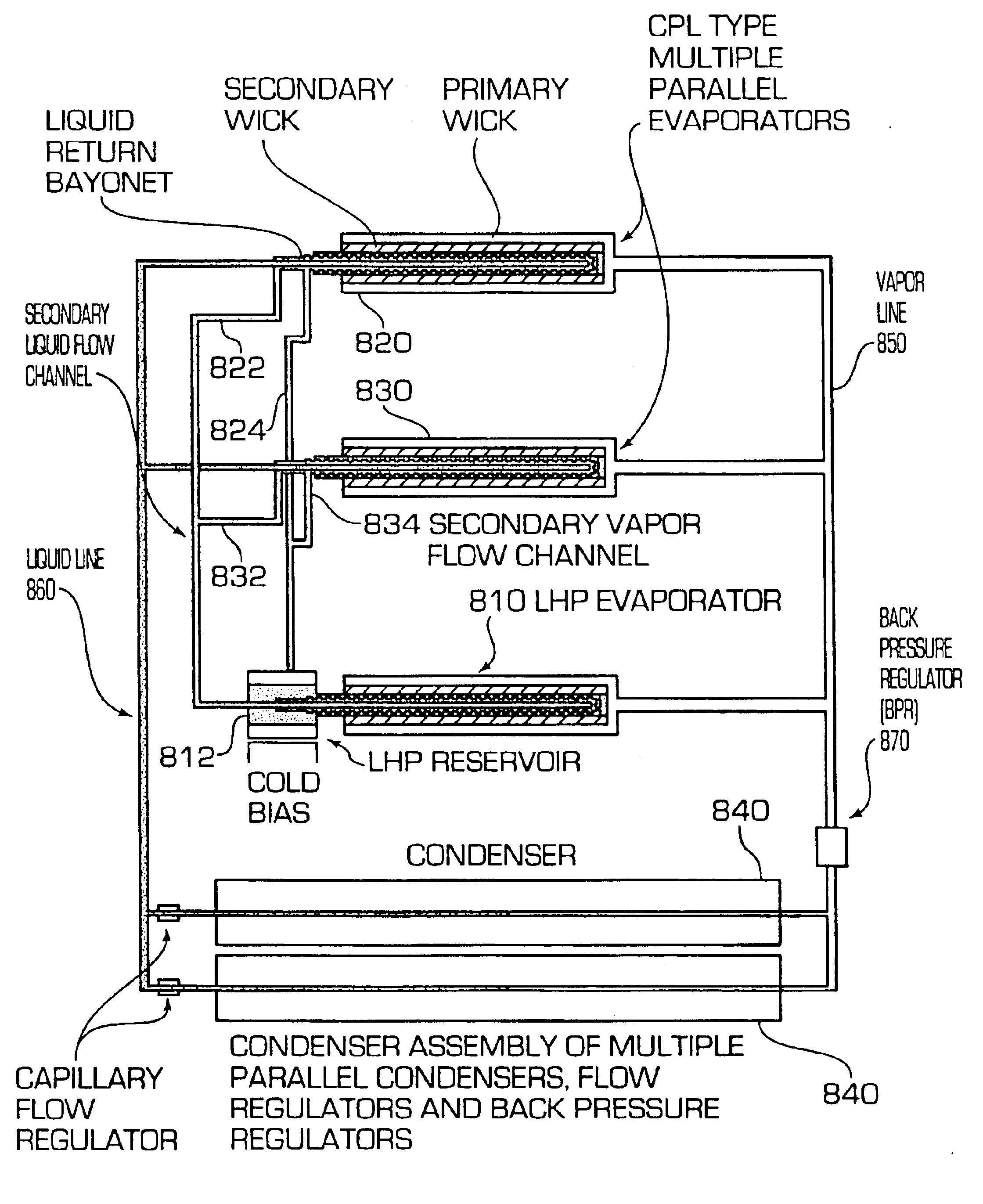
[0048]Referring to FIG. 8, a schematic view of a Hybrid Capillary Pump Loop (HCPL) heat transport system according to an exemplary embodiment of the present invention is illustrated. The secondary loop consists of an LHP evaporator / reservoir assembly 810 that is plumbed in parallel with multiple modified CPL-type evaporators 820, 830 that are plumbed in parallel with one another. Fluid returning from the condensers 840 in the primary loop enters the liquid core of each modified CPL-type evaporators 820, 830 via a bayonet. In the core of each to the modified CPL-type evaporators 820, 830 the returned fluid is handled so that any liquid phase fluid is separated from any vapor or NCG bubbles that may be generated during the operation of the HCPL and have found their way into the core.

[0049]Most of the liquid in the cores of each of the modified CPL-type evaporators 820, 830 is pumped out through the primary wick. The balance of the liquid in each CPL evaporator core is coupled out via ...


PUM


Abstract

A capillary pump two phase heat transport system that combines the most favorable characteristics of a capillary pump loop (CPL) with the robustness and reliability of a loop heat pipe (LHP). Like a CPL, the hybrid loop has plural parallel evaporators, plural parallel condensers, and a back pressure flow regulator. Unlike CPLs, however, the hybrid system incorporates elements that form a secondary loop, which is essentially a LHP that is co-joined with a CPL to form an inseparable whole. Although secondary to the basic thermal management of the system thermal bus, the LHP secondary loop portion of the system provides for important operational functions that maintain healthy, robust and reliable operation. The LHP secondary loop portion provides a function of fluid management during start-up, steady state operation, and heat sink/heat source temperature and power cycling.

Description

CROSS REFERENCE TO RELATED APPLICATION[0001]This application claims priority under 35 U.S.C. §119(e) from provisional application no. 60 / 215,588, filed Jun. 30, 2000. The Ser. No. 60 / 215,588 application is incorporated by reference herein, in its entirety, for all purposes.INTRODUCTION[0002]The present invention relates generally to the field of heat transport. More particularly, the present invention relates to loop heat pipes having plural capillary evaporator structures wherein phase of the working fluid is controlled to maintain system stability.BACKGROUND OF THE INVENTION[0003]Loop Heat pipes (LHPs) and Capillary Pumped Loops (CPLs) are passive two-phase heat transport systems that utilize the capillary pressure developed in a fine pored evaporator wick to circulate the system's working fluid. CPLs, which were developed in the United States, typically feature one or more capillary pumps or evaporators, while LHPs, which originated in the former Soviet Union, are predominantly s...

Claims


Application Information

Patent Timeline
Patent Type & Authority Patents(United States)
IPC IPC(8): F25B23/00F28D15/04
CPCF28D15/043F25B23/006
Inventor KROLICZEK, EDWARD J.WOLF, SR., DAVID A.YUN, JAMES SEOKGEUN
Owner NORTHROP GRUMMAN SYST CORP
Why Eureka
Try Eureka