Castellated turbine airfoil

a turbine and airfoil technology, applied in the direction of liquid fuel engines, vessel construction, marine propulsion, etc., can solve the problems of reducing the overall efficiency of the engine, increasing the complexity of the design, and the cooling of the turbine airfoil

Inactive Publication Date: 2005-05-10
GENERAL ELECTRIC CO
View PDF9 Cites 30 Cited by
  • Summary
  • Abstract
  • Description
  • Claims
  • Application Information

AI Technical Summary

Benefits of technology

[0013]Accordingly, it is desired to provide a turbine airfoi...

Problems solved by technology

However, any air bled from the compressor correspondingly decreases the overall efficiency of the engine, and therefore should be minimized.
And, it is common to use the same cooling air for multiple cooling functions in a single turbine airfoil, which additionally increases the complexity of the design since the various cooling functions are then interrelated, with the upstream cooling features affecting...

Method used


Image

  • Castellated turbine airfoil
  • Castellated turbine airfoil
  • Castellated turbine airfoil

Examples


Embodiment Construction

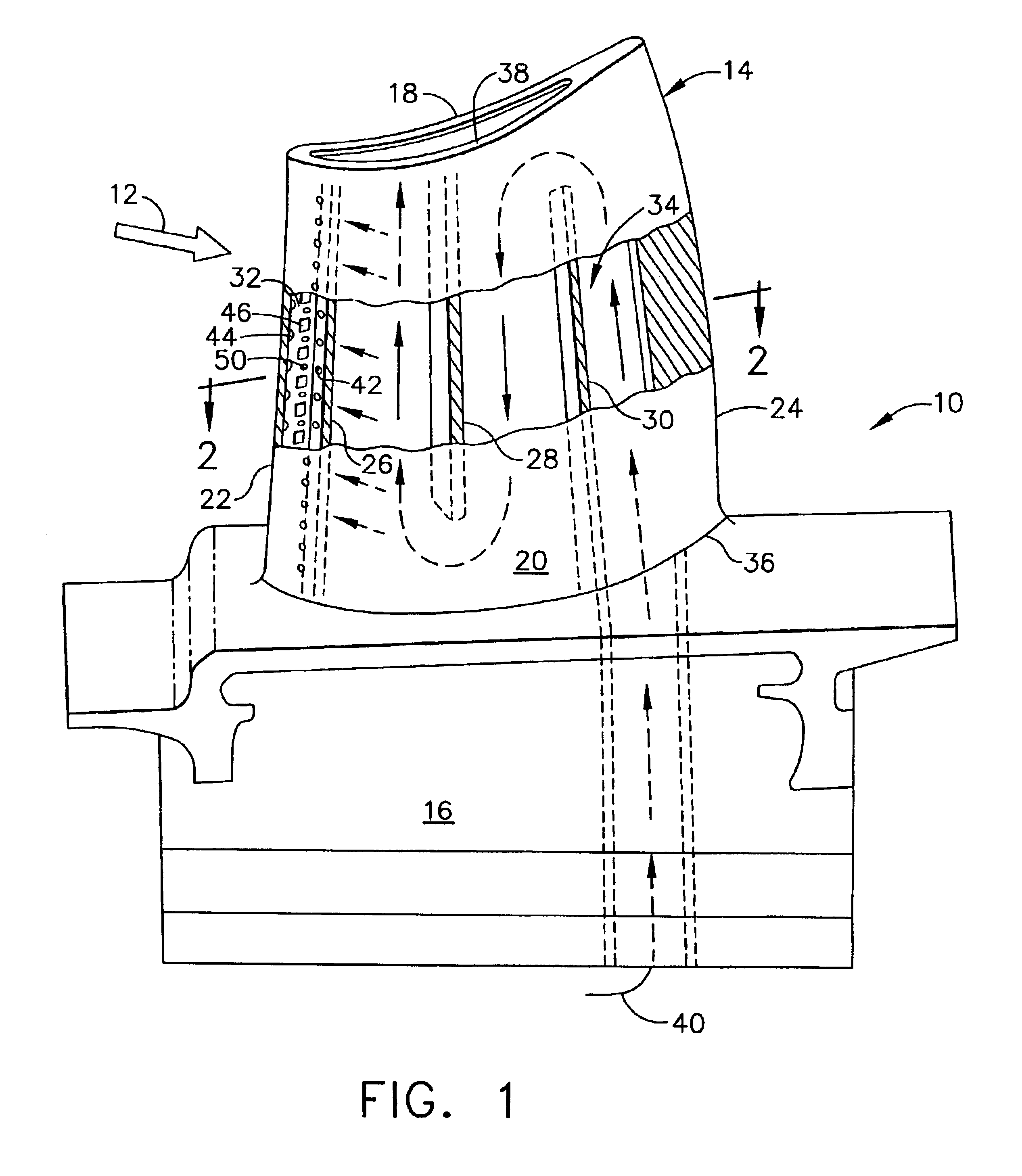
[0020]Illustrated in FIG. 1 is an exemplary first stage turbine rotor blade 10 for a gas turbine engine which extracts energy from combustion gases 12 discharged from a combustor during operation. The blade includes a hollow airfoil 14 extending radially or longitudinally outwardly from an integral mounting dovetail 16. The blade is typically manufactured by casting in a unitary component.

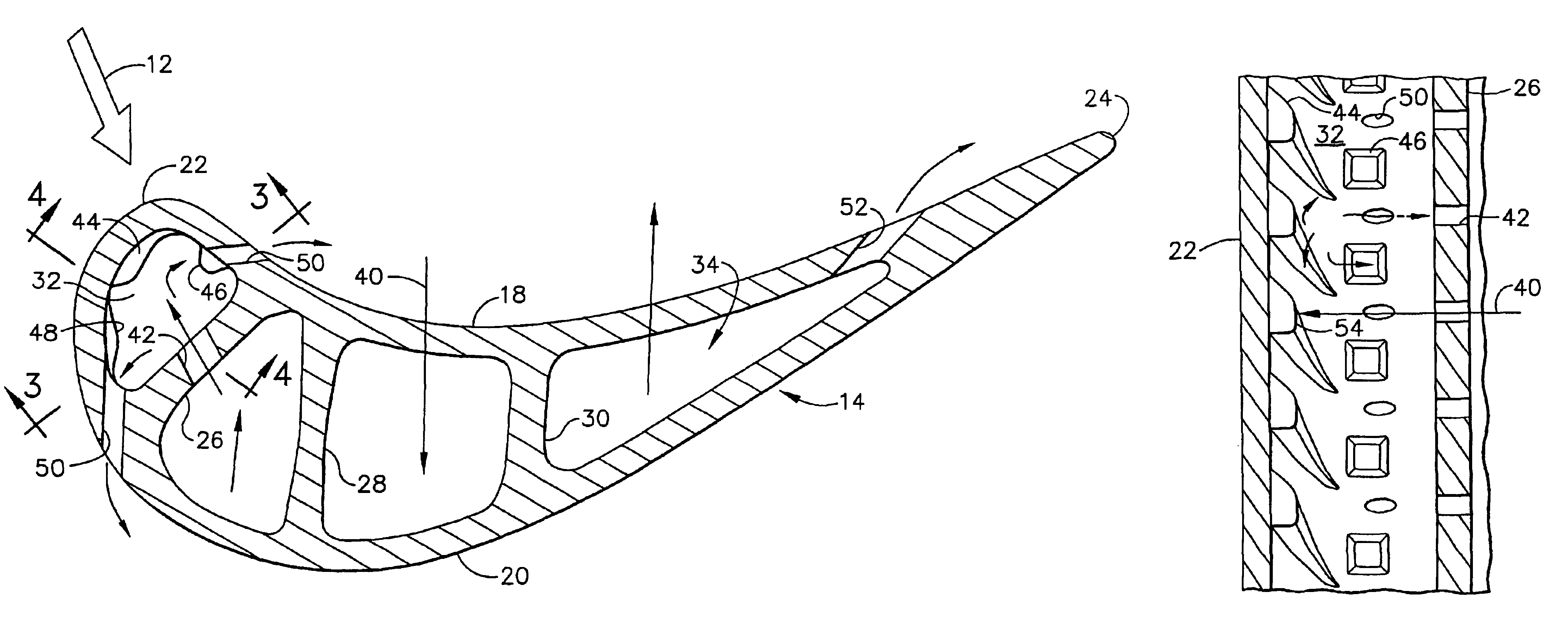
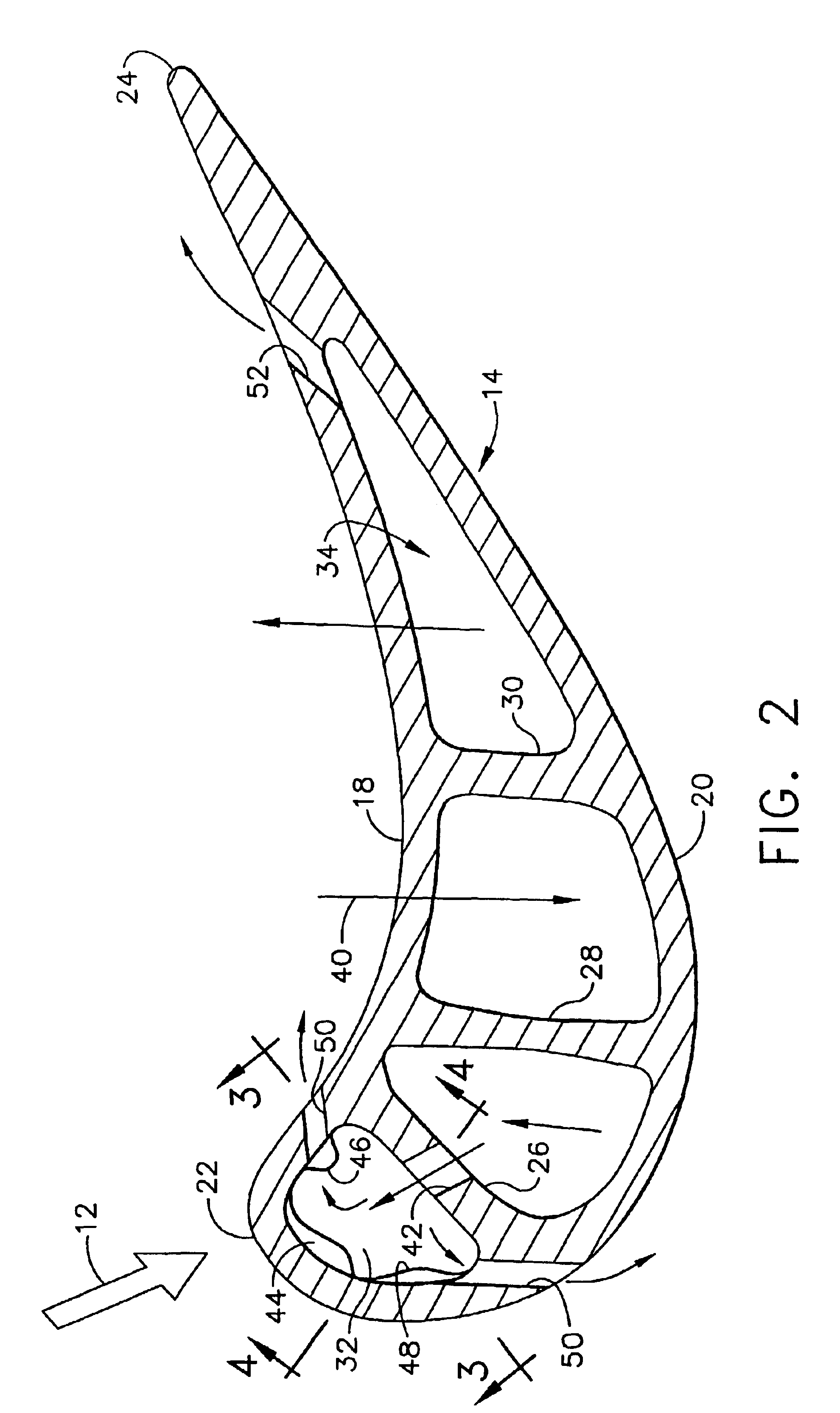
[0021]As shown in FIGS. 1 and 2, the airfoil includes a generally concave first or pressure sidewall 18 integrally joined to a circumferentially or laterally opposite, generally convex second or suction sidewall 20 at axially opposite leading and trailing edges 22,24. The two sidewalls are also integrally joined together at a forward bridge 26 spaced behind the leading edge, a midchord bridge 28 spaced therebehind, and an aft bridge30 spaced between the midchord bridge and the trailing edge of the airfoil.

[0022]The multiple bridges define a first or leading edge flow channel 32 extending directly b...


PUM


Abstract

A turbine airfoil includes pressure and suction sidewalls joined together at opposite leading and trailing edges, and at a forward bridge spaced behind the leading edge to define a flow channel. The bridge includes a row of impingement holes. The flow channel includes a row of fins behind the leading edge, a row of first turbulators behind the pressure sidewall, and row of second turbulators behind the suction sidewall. The fins and turbulators have different configurations for increasing internal surface area and heat transfer for back side cooling the leading edge by the cooling air.

Description

[0001]The U.S. Government may have certain rights in this invention in accordance with Contract Number DAAE07-00-C-N086 awarded by the Department of the Army.BACKGROUND OF THE INVENTION[0002]The present invention relates generally to gas turbine engines, and, more specifically, to turbine airfoil cooling.[0003]In a gas turbine engine, air is pressurized in a compressor and mixed with fuel in a combustor for generating hot combustion gases which flow downstream through several turbine stages. A high pressure turbine (HPT) includes first stage turbine rotor blades extending outwardly from a supporting rotor disk which is rotated by the gases for powering the compressor. A low pressure turbine (LPT) follows the HPT and includes corresponding rotor blades which extract additional energy from the gases for performing useful work such as powering an output drive shaft. In one example, the shaft may be connected to a transmission for powering a military vehicle such as a battle tank.[0004]...

Claims


Application Information

Patent Timeline
IPC IPC(8): F01D5/18F01D5/02F01D5/08
CPCF01D5/186F01D5/187F05D2250/185F05D2250/12F05D2260/22141F05D2250/11F05D2260/201F05D2260/202F05D2250/182
Inventor DEMERS, DANIEL EDWARDTASLIM, MOHAMMAD ESMAAIL
Owner GENERAL ELECTRIC CO
Why Eureka
Try Eureka