Biaxial press molding system

a press molding and axial technology, applied in the direction of press rams, dough shaping, manufacturing tools, etc., can solve the problems of frame damage or excessive noise and vibration, large manpower and time needed when the frame is installed, disassembled or repaired, and large manpower and time needed. to achieve the effect of fine control of pressur

Inactive Publication Date: 2005-05-10
KIM YOUNG JUNG
View PDF6 Cites 6 Cited by
  • Summary
  • Abstract
  • Description
  • Claims
  • Application Information

AI Technical Summary

Benefits of technology

[0008]To solve the above-described problems, it is an object of the present invention to provide an upper and lower biaxial press molding system in which a repulsive force generated during pressing concentrates only on the rotation shaft, so that an optimal design of the frame and a light system are possible, the upper and lower pressure continuously applied to a pressed object can be changed and the maximum pressure can be freely maintained, increased and decreased by forming upper and lower portions at the frictional surfaces of the cams facing each other, a fine control of pressure is possible, the pressure can be appropriately distributed according to part of the pressed object, and mass production of accurate molding products is possible by controlling the pressing point of time.

Problems solved by technology

Accordingly, since an instantaneous impact amount or pressing force of the punch concentrates on the frame only, the frame is damaged or excessive noise and vibrations are generated.
Thus, the molding apparatuses using the conventional presses require very huge and heavy frames so that a lot of manufacturing cost is needed.
Also, a lot of manpower and time is needed when the frame is installed, disassembled or repaired.
However, accurate control of the upper and lower pressures is not possible and mechanism thereof becomes complicated.
As a result, the total size of the press increases.
Furthermore, since the conventional molding apparatus uses an eccentric cam in which the center axis and the rotation axis are eccentric to convert the rotation motion of the cam to linearly reciprocating motion, only a point of time that is the pressure at the maximum point can be controlled while a change in continuously changing pressure cannot be controlled.

Method used


Image

  • Biaxial press molding system
  • Biaxial press molding system
  • Biaxial press molding system

Examples


Embodiment Construction

[0025]Hereinafter, the biaxial press molding system according to a preferred embodiment of the present invention will not be described with reference to the attached drawings.

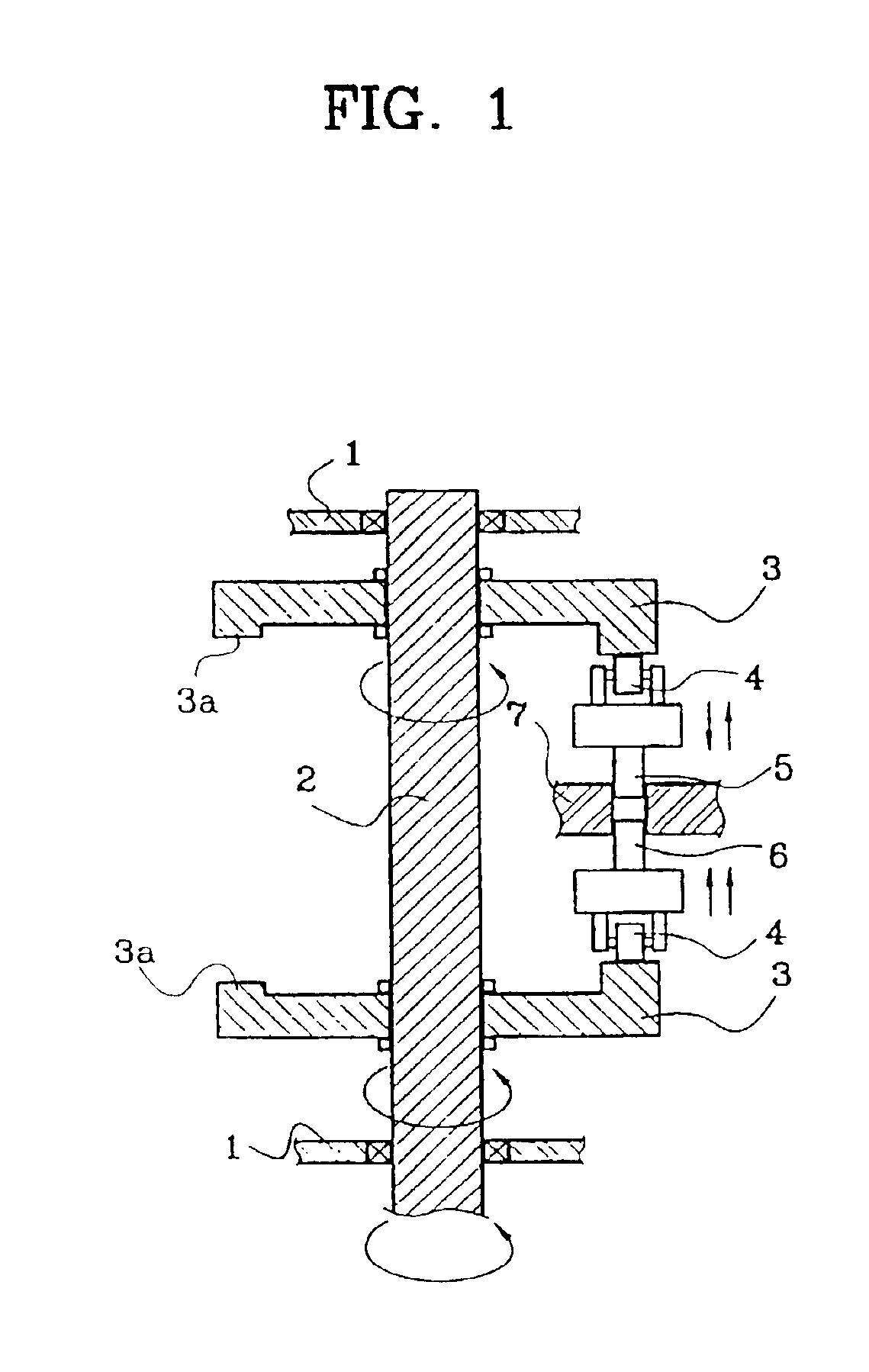
[0026]First, as shown in FIG. 1, but not limited thereto, the biaxial press molding system according to the present invention is based on the technical concept of converting rotational motion of cams 3 rotatably supported at a frame 1 and installed at the same rotation shaft 2 facing each other to linearly reciprocating motion of an upper punch 5 and a lower punch 6 contacting each of the cams 3 through rollers 4.

[0027]Here, the two facing cams 3 are discs. A contact surface between each cam 3 and each roller 4 is a lower surface or an upper surface of the cams 3 facing each other, not the circumferential surfaces of the cams 3.

[0028]That is, each cam 3 is in contact with each roller 4 to make a right angle. The contact surfaces formed on the lower surface and the upper surface of the disc type cams 3 have step...


PUM

PropertyMeasurementUnit
pressureaaaaaaaaaa
rotational forceaaaaaaaaaa
speedaaaaaaaaaa

Abstract

A biaxial press molding system includes a cam apparatus having cams facing each other, and a biaxial press apparatus, disposed between the cams and installed to be capable of sliding contacting the cams, for forming a biaxial pressure to a molding object by converting rotational motion of the cams to linear reciprocating motion. Thus, a repulsive force generated during pressing concentrates only on the rotation shaft, so that an optimal design of the frame and a light system are possible. The upper and lower pressure continuously applied to a pressed object can be changed and the maximum pressure can be freely maintained, increased and decreased by forming upper and lower portions at the frictional surfaces of the cams facing each other. Also, a fine control of pressure is possible, the pressure can be appropriately distributed according to part of the pressed object, and mass production of accurate molding products is possible by controlling the pressing point of time.

Description

BACKGROUND OF THE INVENTION[0001]1. Field of the Invention[0002]The present invention relates to a biaxial press molding system, and more particularly, to a biaxial press molding system in which rotation motion is converted to linear motion by using disc type cams facing each other and a repulsive force generated during the conversion is applied to a rotating plate and a rotation shaft so that the strength and load of a frame can be reduced.[0003]2. Description of the Related Art[0004]In general, a press is a machine for pressing a molded object by changing rotation motion of a motor to a linearly reciprocating motion. The press is designed such that the strength and load of a frame according to pressure applied to the molded object is reinforced. In particular, in molding apparatuses using the conventional presses, a motor rotates a cam and a punch is installed at a mobile body linearly reciprocating corresponding to the rotating cam, so that the punch hits a molded object placed o...

Claims


Application Information

Patent Timeline
Patent Type & Authority Patents(United States)
IPC IPC(8): B30B11/02B30B1/26B30B1/00
CPCB30B1/261B30B11/027Y10S425/005B30B11/007B30B15/302B30B1/00
Inventor KIM, YOUNG-JUNG
Owner KIM YOUNG JUNG
Why Eureka
Try Eureka