Surgical method of treating scoliosis

Inactive Publication Date: 2005-05-10
HOWMEDICA OSTEONICS CORP
View PDF14 Cites 19 Cited by
  • Summary
  • Abstract
  • Description
  • Claims
  • Application Information

AI Technical Summary

Benefits of technology

[0038]More particularly, with respect to the various spacers of the present invention, in its most basic form, the spacers comprise a plurality of sequentially axially wider disc spacer elements, the sequential insertion and removal of which, into an intervertebral space effects a widening of the intervertebral space, such that a desired anatomical spacing of adjacent vertebral bones may be restored. These spacers may include beveled upper and lower circumferential radial edges which facilitate the application of the desired spreading force to the adjacent vertebral bones. For the ease of surgical use, these spacers may each include an engagement locus which couples with a corresponding insertion and removal tool to facilitate the same. This locus comprises an axially medial groove into which said insertion and removal tool can be seated. In two alternative embodiments, the medial groove may comprises a constant width, such that each disc spacer element may rota

Problems solved by technology

Scoliosis is a very common one of these types of irregularities, resulting in a sequential misalignment of the bones and intervertebral discs of the spine.
In severe

Method used


Image

  • Surgical method of treating scoliosis
  • Surgical method of treating scoliosis
  • Surgical method of treating scoliosis

Examples


first embodiment

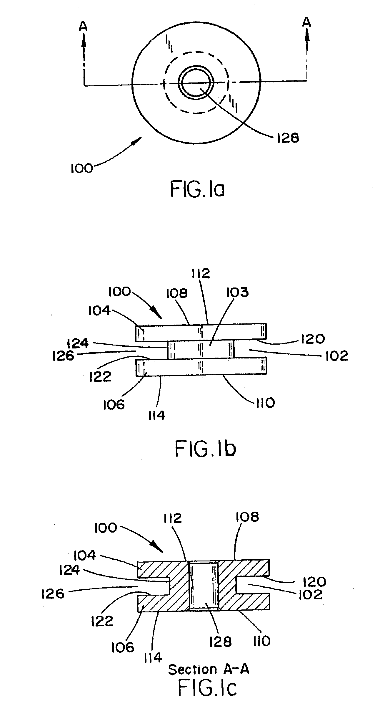
[0073]Referring now to FIGS. 1a-c, an intervertebral trial spacer 100 of the invention is illustrated in side, top and side cutaway views, respectively. The spacer 100 is a cylindrical disc with an annular groove 102 that forms a central trunk 103 and radial flanges 104,106 at each end of the trunk 102. In this embodiment, support portions 108,110 of the top and bottom surfaces 112,114 of the disc are parallel. Further in this embodiment, the walls 120,122 of the annular groove 102 are parallel, such that the floor 124 of the groove 102 is as wide as the opening 126 of the groove 102. Further in this embodiment, the spacer 100 has a central bore 128.

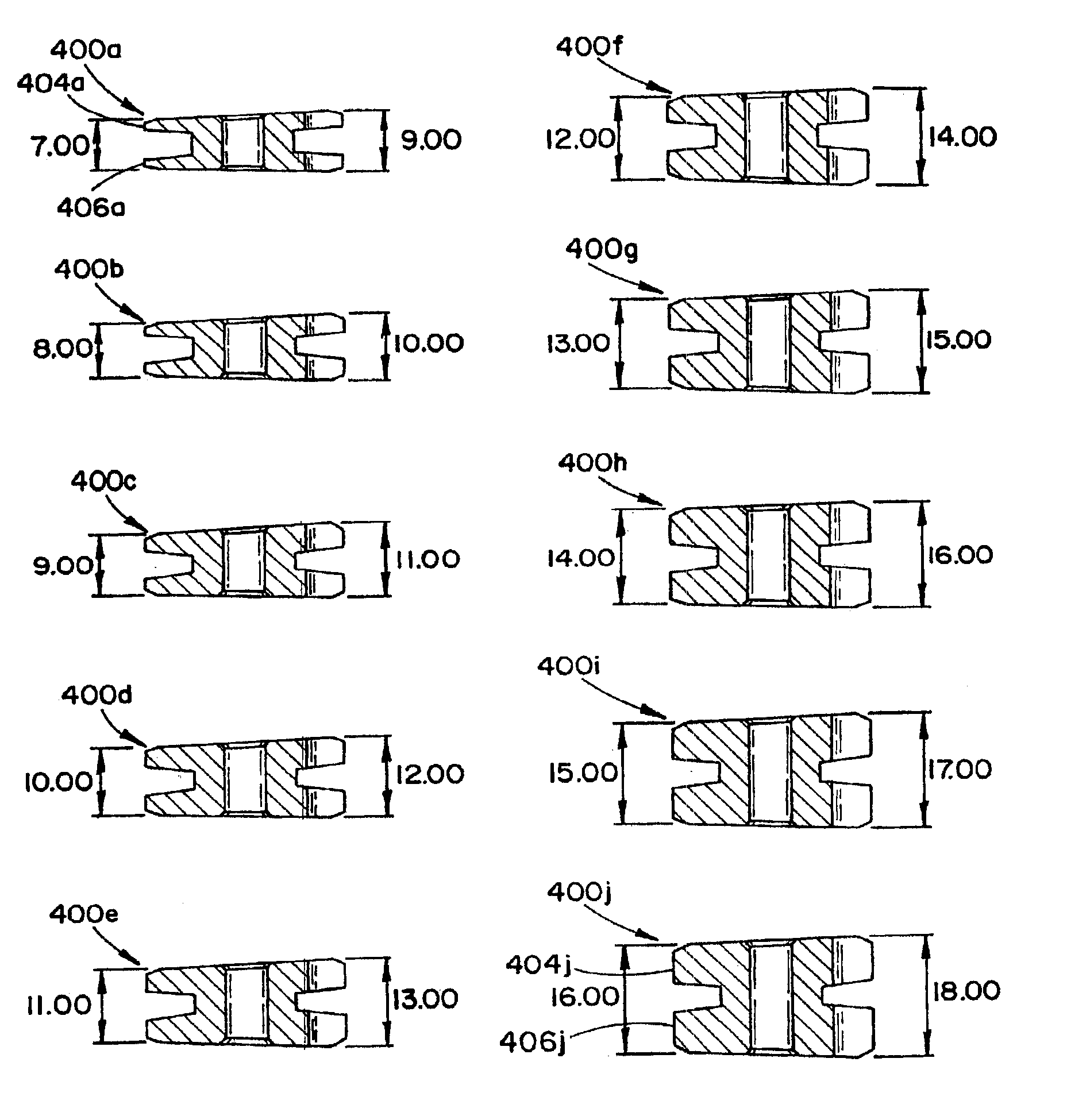
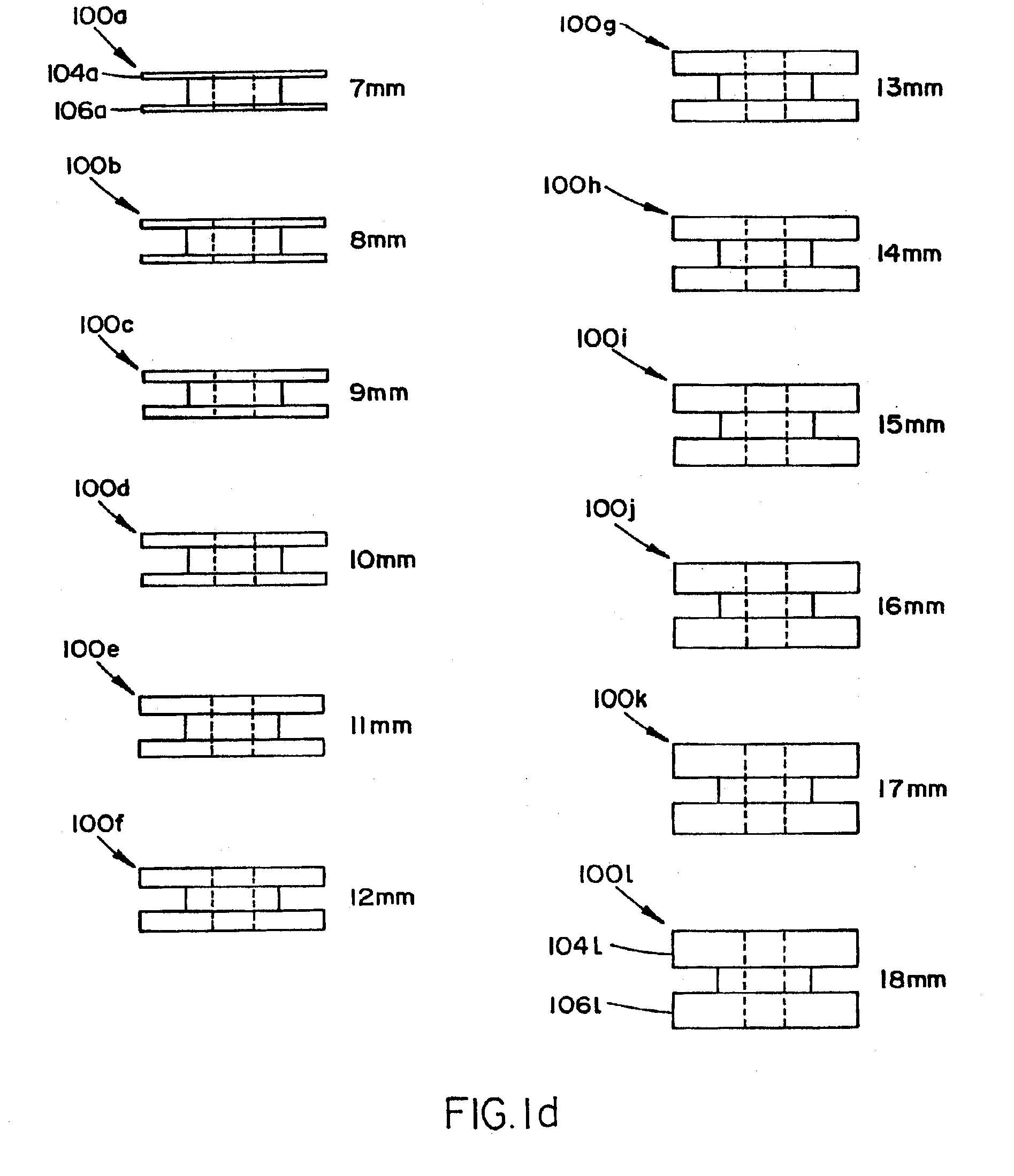
[0074]Referring now to FIG. 1d, a set of intervertebral spacers 100a-l of the invention are illustrated in a side view. Each spacer 100a-l is formed generally similarly to the intervertebral spacer 100 of FIGS. 1a-c, except that each spacer 100a-l has a predetermined depth (denoted by the preferred dimension identified adjacent each spac...

second embodiment

[0075]Referring now to FIGS. 2a-c, an intervertebral spacer 200 of the invention is illustrated in side, top and side cutaway views, respectively. Similarly to the spacer 100, the spacer 200 is a cylindrical disc with an annular groove 202 that forms a central trunk 203 and radial flanges 204,206 at each end of the trunk 202. However, in this embodiment, the flanges 204,206 are radially tapered in that support portions 208,210 of the top and bottom surfaces 212,214 of the disc are parallel, while an outer edge 216 of the top surface 212 is tapered toward an outer edge 218 of the bottom surface 214. Further in this embodiment, in contrast to the spacer 100, the walls 220,222 of the annular groove 202 are tapered toward one another with the increasing depth of the groove 202, such that the floor 224 of the groove 202 is more narrow than the opening 226 of the groove. Further in this embodiment, the spacer 200 has a central bore 228.

[0076]Referring now to FIG. 2d, a set of intervertebr...

third embodiment

[0088]More particularly, the surgeon inserts the tapered trial spacers into the intervertebral space (presumably from the anterior, or anterio-lateral, approach) with the narrow edge of the trial spacer forming a wedge and sliding between the adjacent bones. By utilizing either a second or third embodiment of the spacer insertion tool, described more fully hereinafter with respect to FIGS. 7a-c and 8a-c respectively, the surgeon may turn the spacer around its axis within the intervertebral space to find the most appropriate rotational position (corresponding to the most desirable straightening effect on the spinal column). Stated alternatively, each of the tapered trial spacers has an overall wedge shape that generally corresponds to the pathological tapering of the adjacent bones that characterizes scoliosis. By rotating the wedge-shaped spacer after it has been placed between the adjacent bones, the overall disc alignment may be compensated, restoring appropriate anatomical status...


PUM


Abstract

A surgical treatment for restoring proper anatomical spacing and alignment to vertebral bones including: determining an angular misalignment associated with adjacent vertebral bones; sequentially inserting and removing a series of progressively wider spacer elements into the corresponding intervertebral space between the adjacent vertebral bones until the proper anatomical spacing between the adjacent vertebral bones is restored; for each intervertebral space, inserting a tapered porous spacer element into the intervertebral space between the corresponding adjacent vertebral bones; rotating the tapered porous spacer element such that the rotational orientation of the tapered porous spacer element introduces the appropriate counter offset to the intervertebral space of the previously misaligned scoliotic vertebral bones, thereby restoring the proper anatomical alignment of the vertebral bones; and stabilizing the adjacent vertebral bones to permit infused growth of bone into the tapered porous spacer element.

Description

CROSS REFERENCE TO RELATED APPLICATIONS[0001]The present application is a continuation of U.S. patent application Ser. No. 09 / 906,124, filed Jul. 16, 2001, now U.S. Pat. No. 6,554,864, the disclosure of which is hereby incorporated herein by reference.FIELD OF THE INVENTIONBACKGROUND OF THE INVENTION[0002]The bones and connective tissue of an adult human spinal column consists of more than 20 discrete bones. These more than 20 bones are anatomically categorized as being members of one of four classifications: cervical, thoracic, lumbar, or sacral. They are coupled sequentially to one another by tri-joint complexes that consist of an anterior intervertebral disc and the two posterior facet joints. The anterior intervertebral discs of adjacent bones are cushioning cartilage spacers.[0003]The spinal column of bones is highly complex in that it includes these 20 bones coupled to one another (and others), and it houses and protects critical elements of the nervous system having innumerab...

Claims


Application Information

Patent Timeline
IPC IPC(8): A61F2/44A61F2/46A61F2/00A61F2/30A61B17/02
CPCA61F2/4455A61F2/4611A61F2/44A61B2017/0256Y10S606/907A61F2/4684A61F2002/30166A61F2002/302A61F2002/3023A61F2002/30385A61F2002/30395A61F2002/305A61F2002/30574A61F2002/30616A61F2002/30617A61F2002/30672A61F2002/30772A61F2002/4623A61F2002/4627A61F2002/4628A61F2220/0025A61F2230/0028A61F2230/0065A61F2230/0069A61F2250/0097A61F2/4603
Inventor RALPH, JAMES D.TATAR, STEVENERRICO, THOMAS J.
Owner HOWMEDICA OSTEONICS CORP
Why Eureka
Try Eureka