Method of programming electrons onto a floating gate of a non-volatile memory cell

a floating gate memory cell and electron-programming technology, which is applied in the direction of digital storage, semiconductor devices, instruments, etc., can solve the problems of insufficient memory device design, difficult to optimize the size and formation of memory cell elements, and difficulty in achieving the necessary operational parameters for efficient and reliable operation

Inactive Publication Date: 2005-05-10
SILICON STORAGE TECHNOLOGY
View PDF43 Cites 43 Cited by
  • Summary
  • Abstract
  • Description
  • Claims
  • Application Information

AI Technical Summary

Problems solved by technology

One of the problems facing the manufacturability of semiconductor floating gate memory cell arrays has been the alignment of the various components such as source, drain, control gate, and floating gate.
However, as the dimensions of the floating gate get smaller, this sharp edge can be more difficult to form in this manner.
While the purpose of the step channel is to inject hot electrons more efficiently onto the floating gate, these memory device designs are still deficient in that it is difficult to optimize the size and formation of the memory cell elements as well the necessary operational parameters needed for efficient and reliable operation.

Method used


Image

  • Method of programming electrons onto a floating gate of a non-volatile memory cell
  • Method of programming electrons onto a floating gate of a non-volatile memory cell
  • Method of programming electrons onto a floating gate of a non-volatile memory cell

Examples


first alternate embodiment

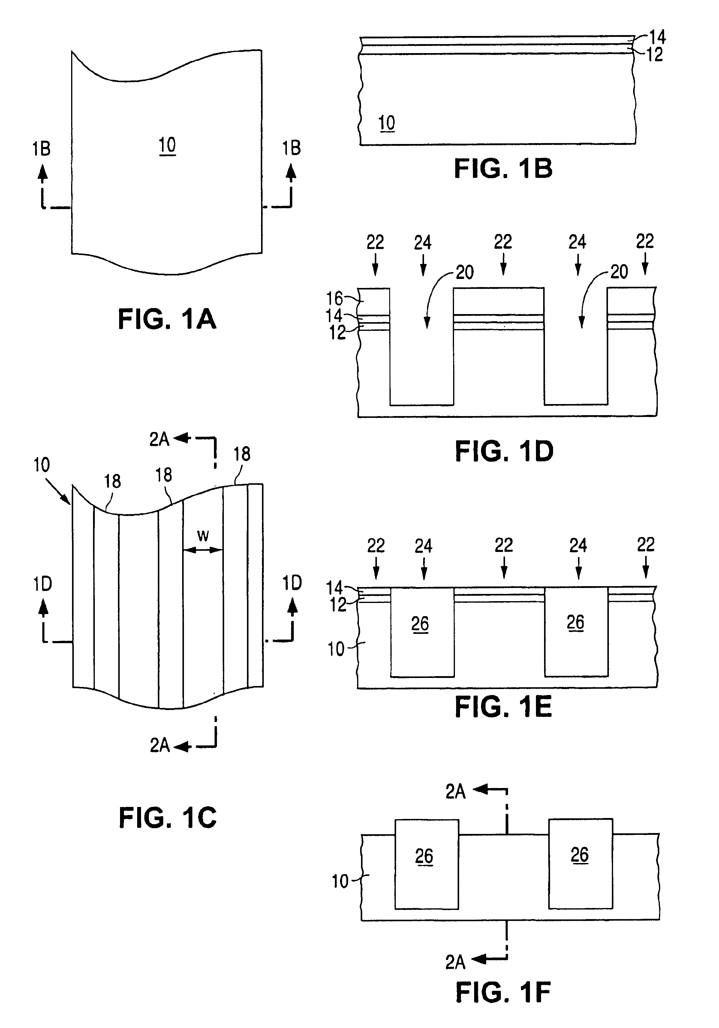
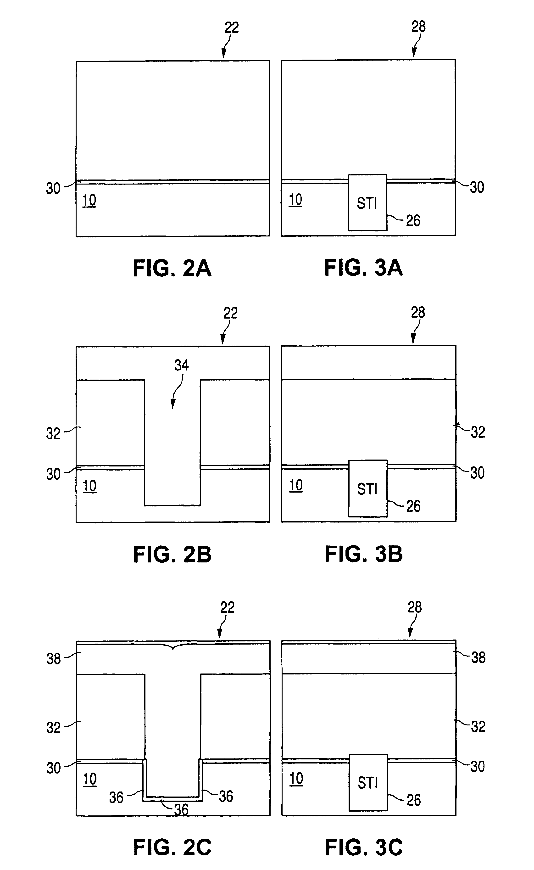
[0062]FIGS. 5A to 5J show the cross sections of the structure in the active regions 22 for an alternate method for making the memory cell array of the present invention. This first alternate process starts with the structure shown in FIG. 2A. For simplicity, elements in common with the first embodiment described above are designated using the same element numbers.

[0063]The thick nitride layer 32 (e.g. ˜1000 to 10,000 Å in thickness) is formed over oxide layer 30. Parallel second trenches 34 are formed in the nitride layer 32 by applying a photo resist (masking) material on the nitride layer 32, and then performing a masking step to remove the photo resist material from selected parallel stripe regions. An anisotropic nitride etch is used to remove the exposed portions of nitride layer 32 in the stripe regions, leaving second trenches 34 that extend down to and expose oxide layer 30. After the photo resist is removed, oxide spacers 102 are formed in second trenches 34 by an oxide dep...

second alternate embodiment

[0072]FIGS. 6A to 6G and 7A to 7G illustrate a second alternate method for making the memory cell array of the present invention. This second alternate process begins with the structures shown in FIGS. 2B and 3B, but without the formation of oxide layer 30 underneath nitride layer 32, as oxide layer 30 is optional for this embodiment. After the formation of insulation material 36 as described above with respect to FIG. 2C, the ion implantation (and possible anneal) process is used to form the first (source) regions 52 in the exposed substrate portions at the bottom of second trenches 34. A thin poly layer 118 is then formed over the structures, as shown in FIGS. 6A and 7A. Poly layer 118 can be doped (e.g. n+) by ion implant, or by an in-situ process. The thickness of poly layer 118 is preferably 50-500 Å, and dictates the eventual thickness of the floating gates for the final memory cell device.

[0073]Oxide is formed over the structure, followed by a planarizing oxide etch (e.g. CMP...

third alternate embodiment

[0081]FIGS. 8A to 8D and 9A to 9D illustrate a third alternate method for making the memory cell array of the present invention. This third alternate process begins with the structures shown in FIGS. 2B and 3B. After the formation of insulation material 36 as described above with respect to FIG. 2C, the ion implantation (and possible anneal) process is used to form the first (source) regions 52 in the exposed substrate portions at the bottom of second trenches 34. Poly spacers 126 are then formed in second trenches 34 by forming a layer of polysilicon over the structure, followed by an anisotropic poly etch that removes the poly layer except for the poly spacers 126, as shown in FIGS. 8A and 9A. The poly spacers preferably have a height no greater than the STI blocks 26 in the isolation regions 24 (e.g. use STI blocks 26 in the inactive regions as an etch stop), which ensures all the polysilicon is removed from the isolation regions.

[0082]Oxide is formed over the structures of FIGS....


PUM


Abstract

A memory cell has a trench formed into a surface of a semiconductor substrate, and spaced apart source and drain regions with a channel region formed therebetween. The source region is formed underneath the trench, and the channel region includes a first portion extending vertically along a sidewall of the trench and a second portion extending horizontally along the substrate surface. An electrically conductive floating gate is disposed in the trench adjacent to and insulated from the channel region first portion. An electrically conductive control gate is disposed over and insulated from the channel region second portion. A block of conductive material has at least a lower portion thereof disposed in the trench adjacent to and insulated from the floating gate, and can be electrically connected to the source region. A method of programming the cell comprises the steps of creating an inversion layer in the second portion of the channel. A stream of electrons is generated at the drain region which is adjacent to the inversion layer, and the stream of electrons is passed through the inversion layer, reaching a pinch off point. The electrons are accelerated through the depletion region by the field lines from the floating gate, with little or no scattering, causing the electrons to be accelerated through the insulator, separating the floating gate from the substrate, and injected onto the floating gate.

Description

[0001]This application is a continuation-in-part application of a co-pending application Ser. No. 10 / 358,623 filed on Feb. 4, 2003, which in turn claims the benefit of U.S. Provisional Application No. 60 / 370,888, filed Apr. 5, 2002, and entitled High Coupling Non-Volatile Trench Memory Cell; U.S. Provisional Application No. 60 / 393,696, filed Jul. 2, 2002, and entitled Non-Volatile Memory Trench Cell and Method of Making Same; and U.S. Provisional Application No. 60 / 398,146, filed Jul. 23, 2002, and entitled Non-Volatile Memory Trench Cell With Buried Floating Gate, all of which are incorporated herein in their entirety by reference.TECHNICAL FIELD[0002]The present invention relates to a self-aligned method of forming a semiconductor memory array of floating gate memory cells. The present invention also relates to a semiconductor memory array of floating gate memory cells of the foregoing type.BACKGROUND OF THE INVENTION[0003]Non-volatile semiconductor memory cells using a floating g...

Claims


Application Information

Patent Timeline
Patent Type & Authority Patents(United States)
IPC IPC(8): H01L21/70H01L21/8247H01L27/105H01L27/115H01L29/788H01L29/792
CPCH01L27/11553H01L27/105H10B41/23
Inventor YEH, BINGKIANIAN, SOHRABHU, YAW WEN
Owner SILICON STORAGE TECHNOLOGY
Why Eureka
Try Eureka