Drive apparatus for PWM control of two inductive loads with reduced generation of electrical noise

a technology of inductive load and drive apparatus, which is applied in the direction of dynamo-electric converter control, multiple dynamo-motor starters, instruments, etc., can solve the problem that signals themselves may become a source of electrical nois

Inactive Publication Date: 2005-05-10
DENSO CORP
View PDF18 Cites 50 Cited by
  • Summary
  • Abstract
  • Description
  • Claims
  • Application Information

AI Technical Summary

Benefits of technology

[0015]It is an objective of the present invention to overcome the above problems of the prior art by providing an inductive load drive apparatus for application to driving two inductive loads mutually separately, whereby only small values of capacitance are required for capacitors that are used in constituting a filter such as a π-configuration filter which is incorporated for absorbing regenerative current flow, and whereby generation of electrical noise due to fluctuations in the supply current of a DC power source such as a vehicle battery which powers the apparatus can be held at a low level.
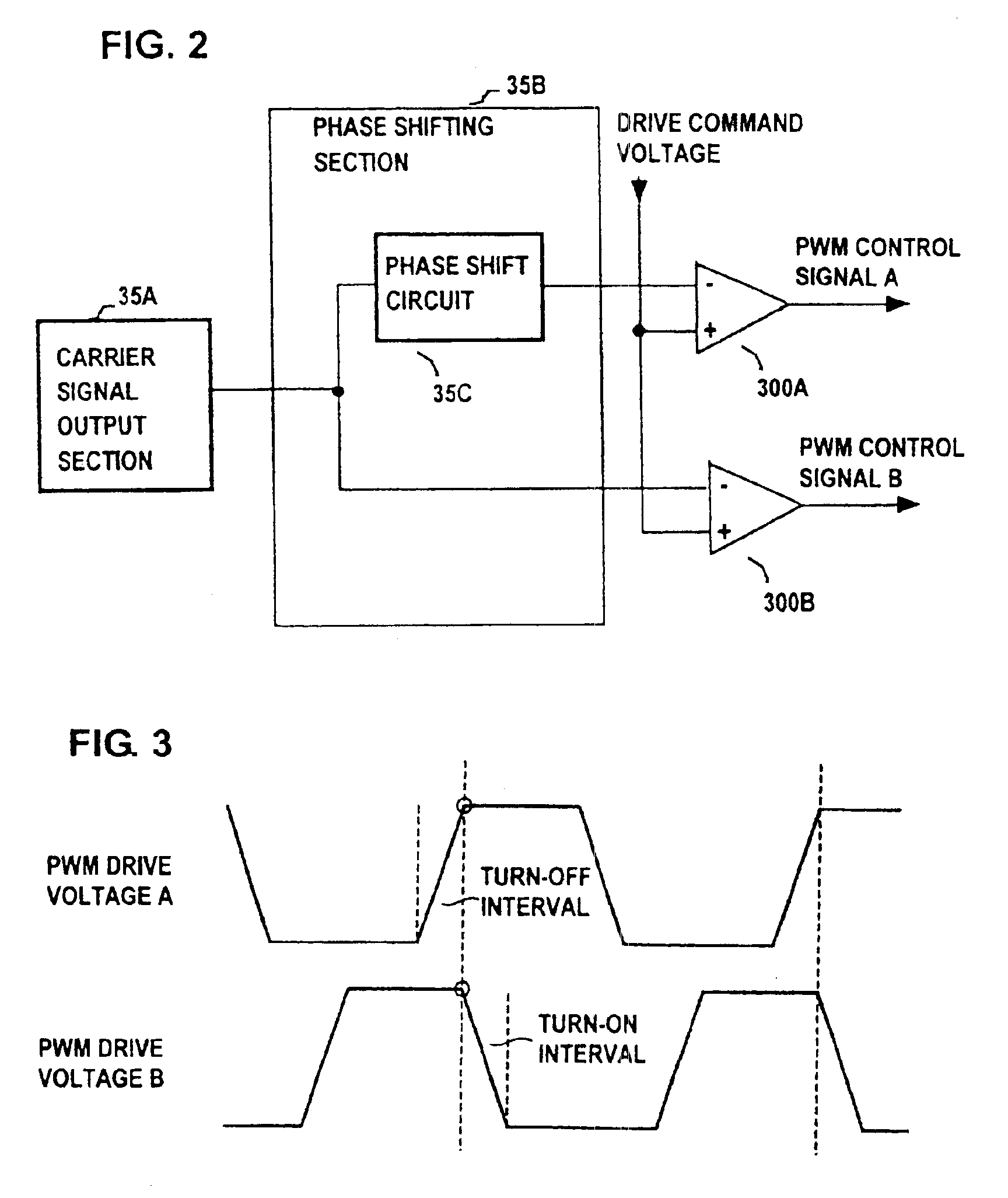
[0018]If the PWM control signals have a high frequency, then these signals themselves may become a source of electrical noise. For that reason, according to another aspect, the control circuit includes waveform shaping circuit means for shaping each of the two PWM control signals to have a trapezoidal waveform. In that way, each of the transitions between the high and low levels of each of the PWM drive voltages produced by the switching elements is made more gradual than is the case for a rectangular waveform, and this is effective in reducing the generation of electrical noise.
[0019]Moreover by forming the waveforms of the PWM control signals with a trapezoidal shape, whereby at each transition, a PWM control signal gradually rises to a level at which the corresponding switching element is set completely in the on (i.e., conducting) state, or gradually falls to a level whereby that corresponding switching element is set in the off (i.e., non-conducting) state, the duration of each of the intervals in which a switching element remains in the on state is made longer with respect to the duration of each interval in which the switching element is in the off state. By applying such a feature to an apparatus configured according to the first aspect of the invention described above, it becomes possible to ensure that the respective intervals in which the two switching elements are in the on state will never coincide, irrespective of the value of duty ratio that is established for the PWM control signals. Hence, further effectiveness in reducing the generation of electrical noise can be achieved.

Problems solved by technology

If the PWM control signals have a high frequency, then these signals themselves may become a source of electrical noise.

Method used


Image

  • Drive apparatus for PWM control of two inductive loads with reduced generation of electrical noise
  • Drive apparatus for PWM control of two inductive loads with reduced generation of electrical noise
  • Drive apparatus for PWM control of two inductive loads with reduced generation of electrical noise

Examples


first embodiment

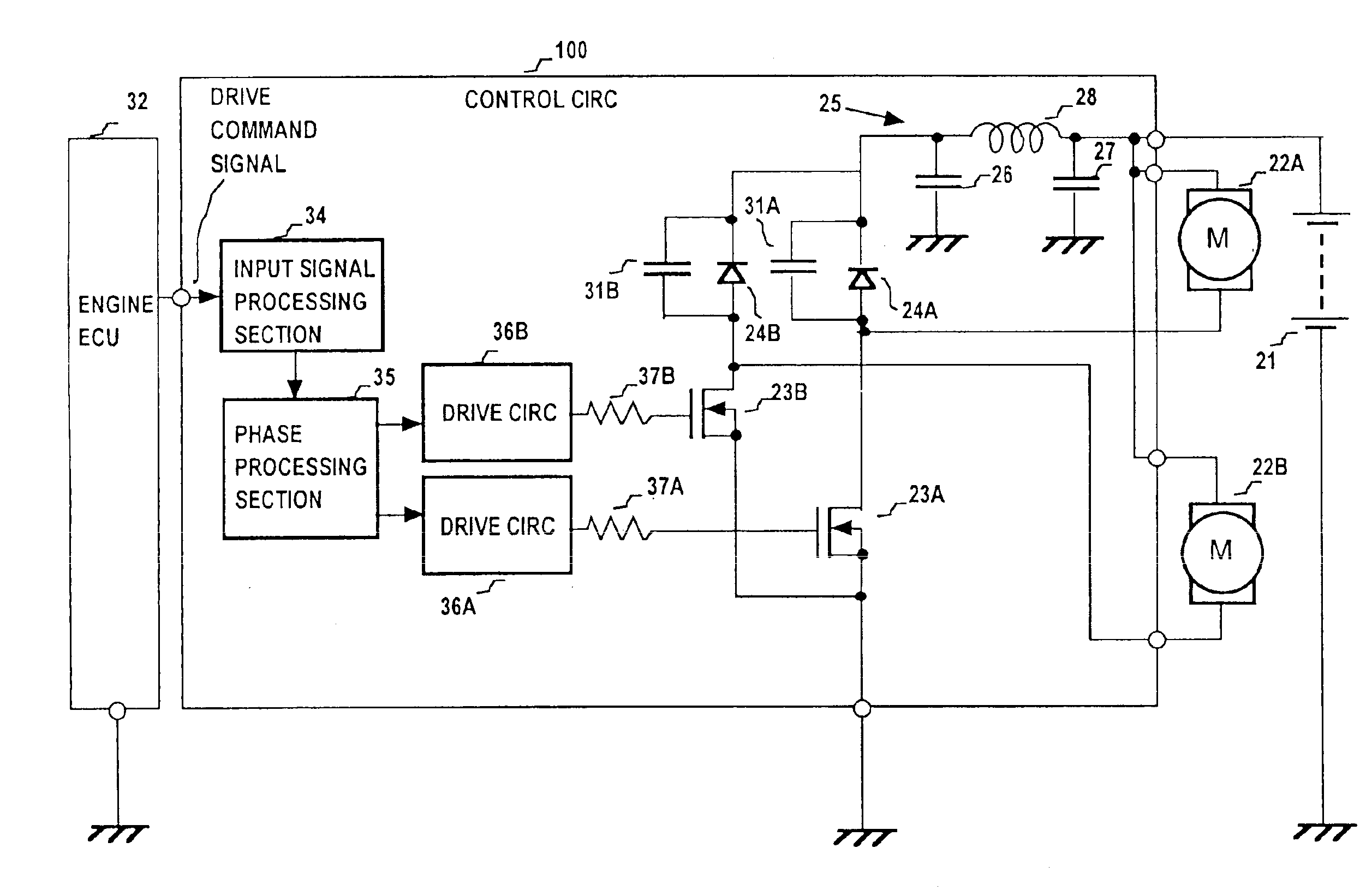
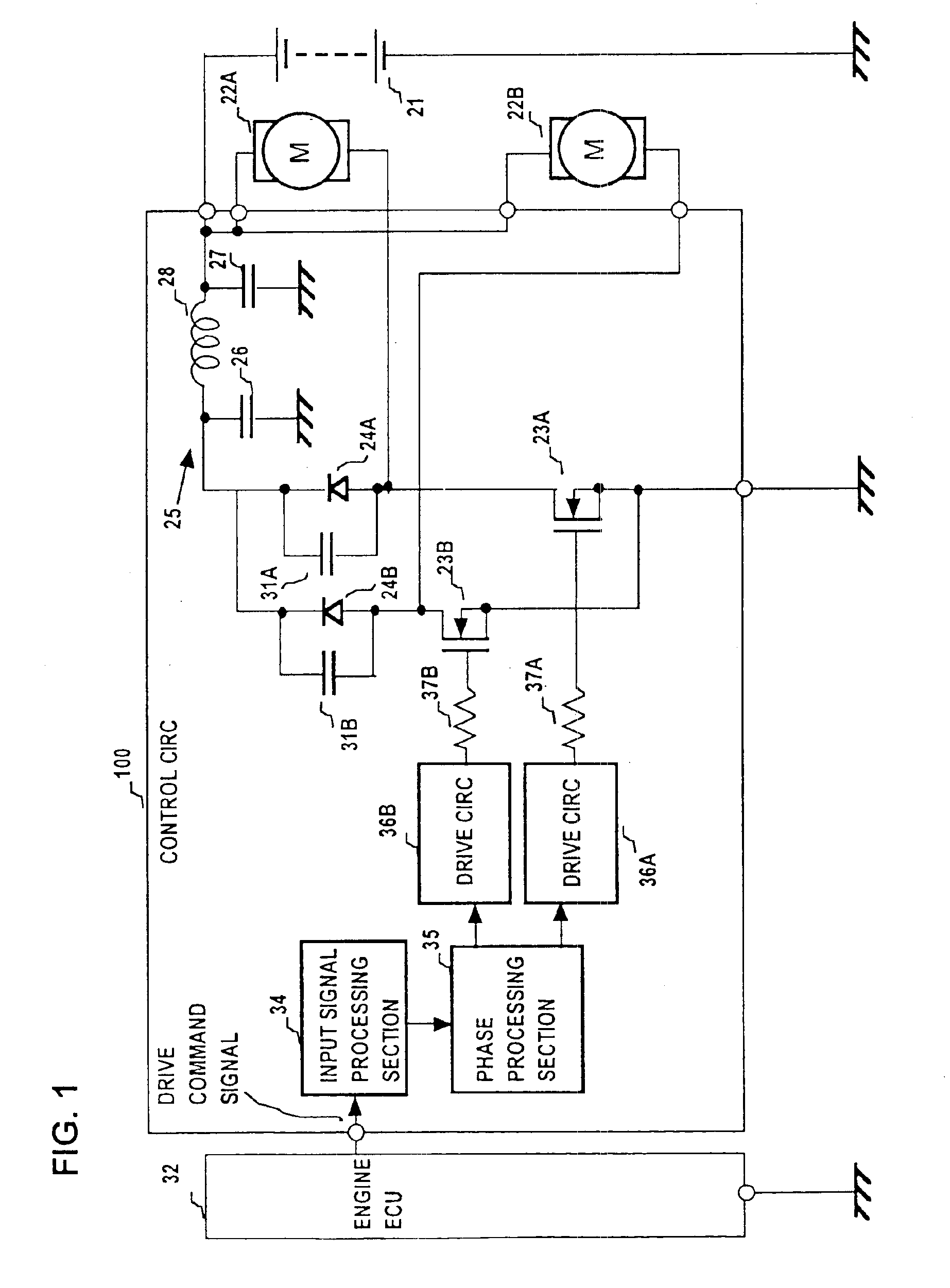
[0063]The motors 122A, 122B are driven by PWM operation by the control circuit 110, with the motor 122A and MOS FET 23A being connected in series between the (positive) potential of the battery 21 and ground potential, and the motor 122B and MOS FET 23B similarly connected in series between the positive potential of the battery 21 and ground potential. The drains of the MOS FETs 23A, 23B are connected through respective diodes 24A, 24B to one side of the π filter 25, with the other side of the filter 25 connected to the positive potential of the battery 21, and with the diodes being connected in a direction such as to be reverse-biased when the corresponding one of the MOS FETs 23A, 23B is set in the on (i.e., conducting) state. Capacitors 31A, 31B for noise suppression are respectively connected in parallel with the diodes 24A, 24B. The n filter 25 is formed of a coil 28 and capacitors 26, 27 as shown. These components correspond in function to the correspondingly numbered componen...

second embodiment

[0080]FIG. 12 shows an example of graphs of the relationship between (average) drive voltage applied to a motor and resultant air flow rate from a fan driven by the motor, for the case of a 100 W and a 160 W motor respectively. As shown, for example the air flow rate produced by the fan of the 160 W motor is 2000 m3 / h with a drive voltage of approximately 5.8 V, whereas it is necessary to apply a drive voltage of 7.0 V to the 100 W motor in order to achieve the same air flow rate. Assuming that the 160 W motor and 100 W motor respectively correspond to the motors 122A, 122B of the second embodiment, it can be understood that the amplification factor of the amplifier 216B can be preset by adjusting the values of the resistors 218B, 219B, 221B, 223B appropriately. That is to say, the amplification factor would be preset such that when a drive voltage of 5.8 V is being supplied to the motor 122A, the duty ratio of switching the FET 23B is increased relative to that of the FET 23A to an...


PUM


Abstract

A drive apparatus for driving two motors by PWM control of respective switching elements connected to the motors, whereby respective control signals are applied to the switching elements such that each commencement of a transition of one of the switching elements from the non-conducting to the conducting state coincides with the termination of a transition of the other switching element from the conducting to the non-conducting state, thereby reducing generated electrical noise, and for supplying equivalent values of drive voltage to two motors of different power ratings which rotate respective cooling fans, to obtain equalized levels of air flow rate.

Description

BACKGROUND OF THE INVENTION[0001]1. Field of Application[0002]The present invention relates to an inductive load drive apparatus for applying PWM (pulse width modulation) control to mutually separately drive a pair of inductive loads that are connected to a DC power source.[0003]2. Description of Prior Art[0004]In the prior art, various methods have been proposed for overcoming the problems that arise when a plurality of loads are driven in parallel, with the driving being based on PWM control signals. For example with Japanese patent 2002-43910, it is ensured that each falling edge of a PWM control signal that controls driving of one of the loads coincides with a rising edge of the PWM control signal that controls driving of the other load, for thereby ensuring that an increase in load current of one of the loads will be cancelled by a decrease in load current of the other load, and so reduce variations in the overall load current. That is to say, if both of the loads were to be su...

Claims


Application Information

Patent Timeline
Patent Type & Authority Patents(United States)
IPC IPC(8): H02M3/158H02M3/04H02P5/68
CPCH02M3/158H02P5/68H02M2003/1555H02M2001/008H02M1/008H02M3/1555
Inventor NAKAMURA, KOJIYOSHIMURA, SATOSHIUSAMI, TAKUYA
Owner DENSO CORP
Why Eureka
Try Eureka