Surface acoustic wave filter apparatus having different structure reflectors

a filter apparatus and surface acoustic wave technology, applied in piezoelectric/electrostrictive/magnetostrictive devices, electrical apparatus, piezoelectric/electrostriction/magnetostriction machines, etc., can solve the disadvantages of inverting regions in which spurious responses are generated with respect to each other, and the attenuation in the frequency region other than the pass band is not sufficient, so as to achieve the effect of further improving the attenuation level

Inactive Publication Date: 2005-05-10
MURATA MFG CO LTD
View PDF13 Cites 7 Cited by
  • Summary
  • Abstract
  • Description
  • Claims
  • Application Information

AI Technical Summary

Benefits of technology

[0016]With this configuration, by providing a plurality of IDTs arranged in the SAW propagating direction, a filtering function, which is determined by the conversion between the electrical signal of each IDT and the SAW, can be exhibited in which the electrical signals in the pass band are allowed to pass with a low insertion loss and the electrical signals outside the pass band are minimized. In addition to the filtering function, the SAW filter device is provided with the balanced-to-unbalanced conversion function. The reflectors for reflecting the SAWs propagating from the IDTs to the IDTs are also provided for the SAW filter device, thereby improving the conversion efficiency from the generated SAWs to the electrical signals.
[0017]Additionally, the structure of at least one of the reflectors is different from that of the other reflector. Thus, the generation of unwanted spurious responses in a region outside the pass band, and in particular, in a region near the pass band, can be minimized, thereby obtaining a sufficient attenuation level.
[0020]With this configuration, the structure of at least one of the reflectors is different from that of the other reflectors. Thus, the generation of unwanted spurious responses in a region outside the pass and, in particular, in a region near the pass band, can be minimized, thereby easily obtaining a sufficient attenuation level even with one stage of filter devices.
[0022]With this configuration, by providing a plurality of stages of filter devices, a balanced-to-unbalanced input / output function having different input / output impedances can be achieved. By differentiating the structures of the reflectors, the generation of unwanted spurious responses in a region outside the pass band, in particular, in a region near the pass band, can be minimized, and the attenuation level can be further improved over that obtained by a SAW filter apparatus having a first stage of filter devices.
[0023]In the aforementioned SAW filter apparatus, the structure of the reflectors of the first group may be different from that of the reflectors of the second group. With this arrangement, the generation of unwanted spurious responses in a region outside the pass band, in particular, in a region near the pass band, can be reliably minimized.
[0026]By using the SAW filter apparatus having a low insertion loss in the pass band and a high attenuation level in a region outside the pass band, in particular, in a region lower than the pass band, and exhibiting excellent transmission characteristics, the communication apparatus exhibits excellent communication characteristics.

Problems solved by technology

In the above-configured SAW filter apparatus, however, spurious responses are generated in a region in the vicinity of the pass band due to the excitation of a SAW, and the phase characteristics of the balanced terminals 506 and 507 in the region in which spurious responses are generated are disadvantageously inverted with respect to each other, as in the pass band.
Thus, signals output from the balanced terminals 506 and 507 do not cancel each other out, and the attenuation in the frequency region other than the pass band is not sufficient.

Method used


Image

  • Surface acoustic wave filter apparatus having different structure reflectors
  • Surface acoustic wave filter apparatus having different structure reflectors
  • Surface acoustic wave filter apparatus having different structure reflectors

Examples


Embodiment Construction

[0036]The present invention is described in detail below with reference to FIGS. 1 through 7 through illustration of preferred embodiments.

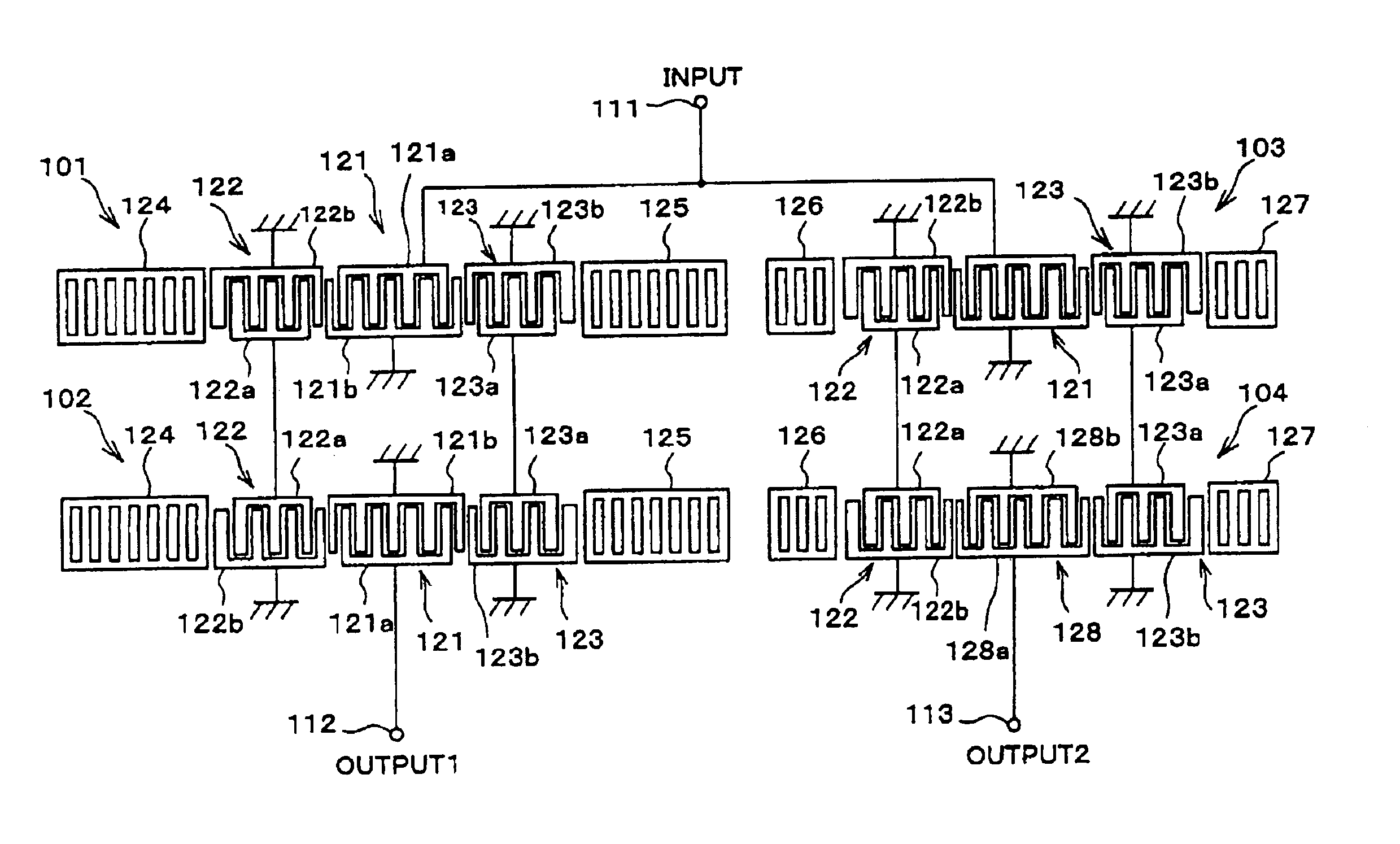
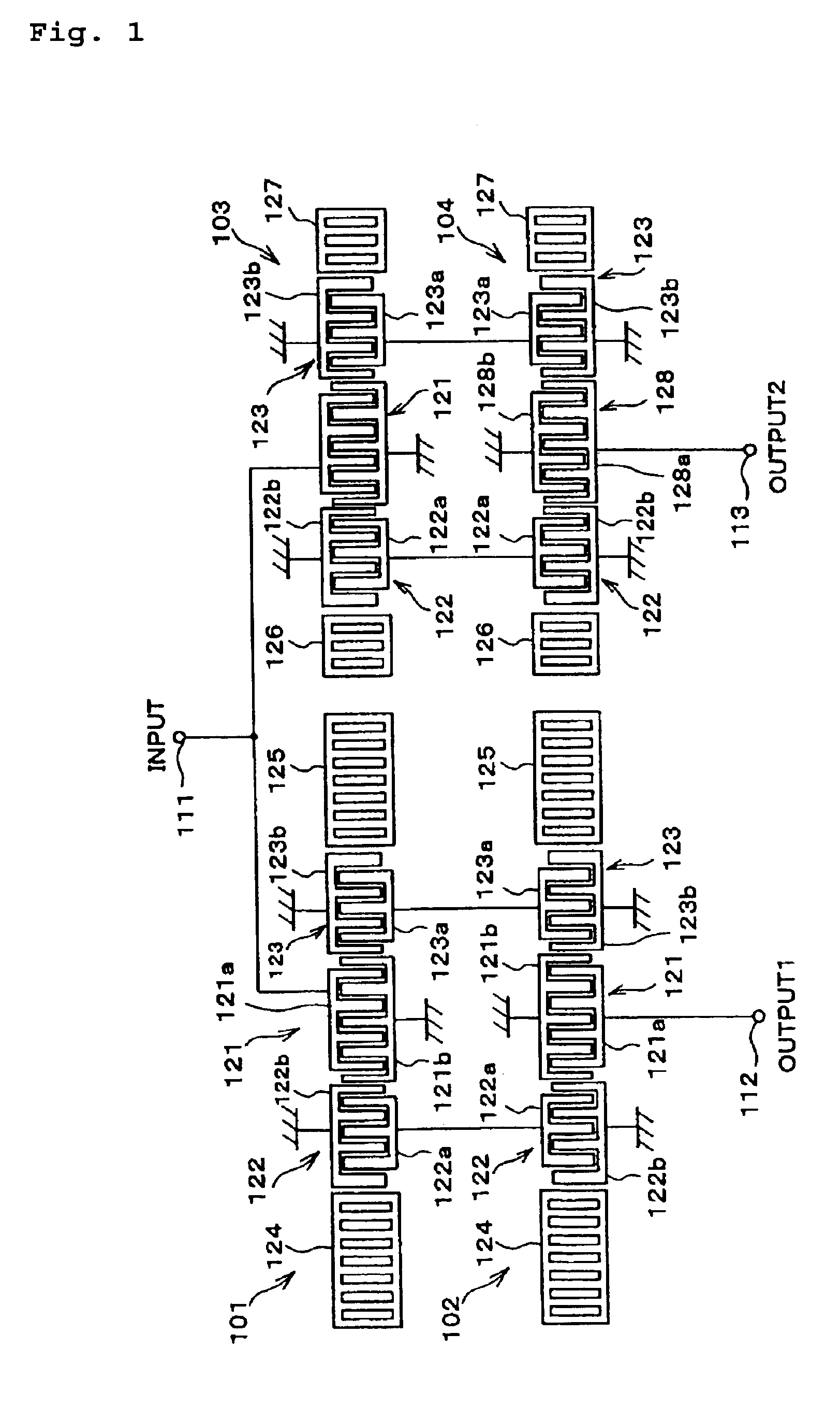
[0037]In a SAW filter apparatus constructed in accordance with a first preferred embodiment of the present invention, as shown in FIG. 1, first through fourth SAW filter devices 101 through 104 are disposed on a piezoelectric substrate. The transmission phase characteristics of the fourth SAW filter device 104 are substantially 180° out of phase with those of the third SAW filter device 103. The piezoelectric substrate is not shown in FIG. 1.

[0038]The first SAW filter device 101 preferably has three IDTs 123, 121, and 122. The IDTs each have a strip-like base portion (bus bar) and two electrode portions provided with a plurality of strip-like electrode fingers. The electrode fingers extend substantially perpendicularly from one side of the base portion such that they are substantially parallel to each other. The electrode fingers also interdigita...


PUM


Abstract

A surface acoustic wave filter apparatus includes extensional-coupling-resonator-mode first through fourth SAW filter devices which are disposed on a piezoelectric substrate. Each SAW filter device includes three interdigital transducers (IDTs) arranged in a SAW propagating direction, and reflectors arranged such that they sandwich the IDTs therebetween. The SAW filter devices have a balanced-to-unbalanced input / output function. The reflectors of the first and second SAW filter devices are different from those of the third and fourth SAW filter devices in at least one of the number, the pitch, the duty, and the thickness of the electrode fingers of the reflectors.

Description

BACKGROUND OF THE INVENTION[0001]1. Field of the Invention[0002]The present invention relates to a surface acoustic wave (SAW) filter apparatus, and more particularly, to a SAW filter apparatus having a balanced-to-unbalanced conversion function and having different impedance characteristics at an input side and an output side of the SAW apparatus. The present invention also relates to a communication apparatus including the above-described SAW filter apparatus.[0003]2. Description of the Related Art[0004]There has been significant technological progress in decreasing the size and the weight of portable communication apparatuses, such as cellular telephones. One way to achieve such results is to reduce the number and the size of the individual components of the communication apparatus. Additionally, components having composite functions are being developed.[0005]In view of this background, research is being actively conducted with respect to a SAW filter apparatus used in an RF stag...

Claims


Application Information

Patent Timeline
Patent Type & Authority Patents(United States)
IPC IPC(8): H03H9/00H03H9/64H03H9/145
CPCH03H9/0085H03H9/0071H03H9/64
Inventor SAWADA, YOICHI
Owner MURATA MFG CO LTD
Why Eureka
Try Eureka