Dynamic gain equalization arrangement for optical signals

a technology of optical signals and equalization arrangements, applied in the field of optical communication, can solve the problems of inconvenient design of large interferometers, inability to reduce the cost of design, and inability to make the final device loss at least 4.5 db, so as to reduce the electrical power consumption, minimize ripple, and maximize the dgef spectral resolution

Inactive Publication Date: 2005-05-10
ALCATEL-LUCENT USA INC +1
View PDF9 Cites 14 Cited by
  • Summary
  • Abstract
  • Description
  • Claims
  • Application Information

AI Technical Summary

Benefits of technology

[0008]The present invention maximizes the DGEF spectral resolution and minimizes ripple. Driving both arms in a push-pull fashion also reduces the electrical power consumption, polarization dependence, and maintains constant power dissipation. The present invention also takes advantage of the introduction ...

Problems solved by technology

However, because the known design had long dissimilar interfering paths, it required polarization diversity to achieve low polarization-dependent loss (PD...

Method used


Image

  • Dynamic gain equalization arrangement for optical signals
  • Dynamic gain equalization arrangement for optical signals
  • Dynamic gain equalization arrangement for optical signals

Examples


Embodiment Construction

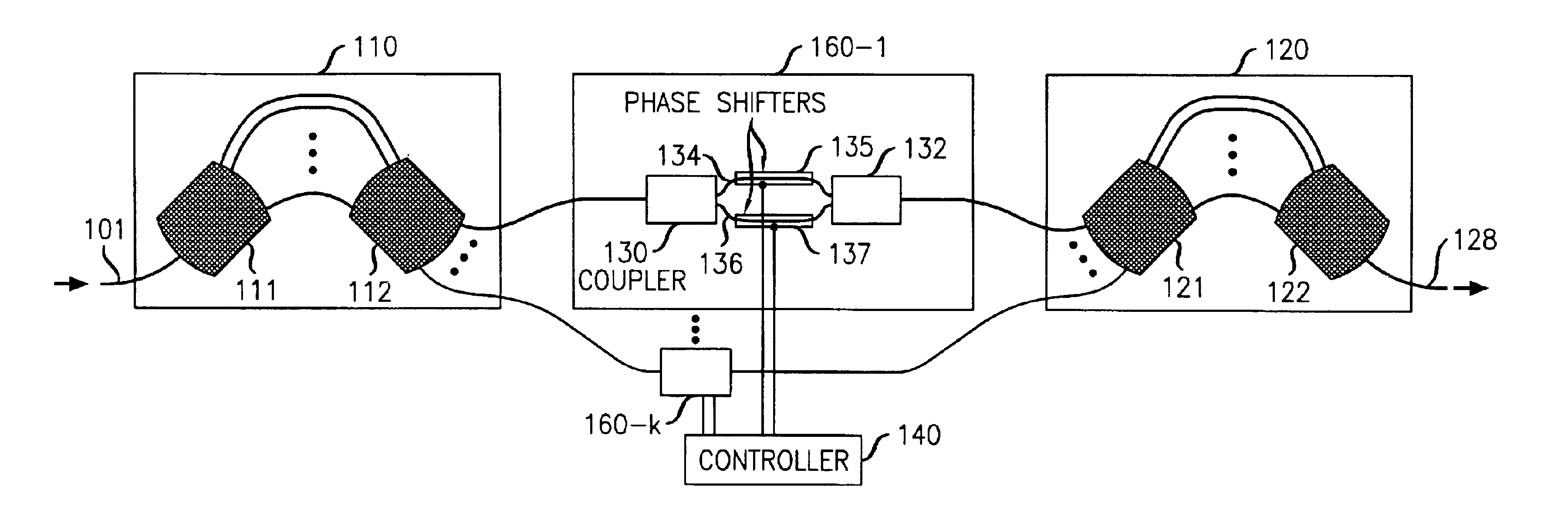
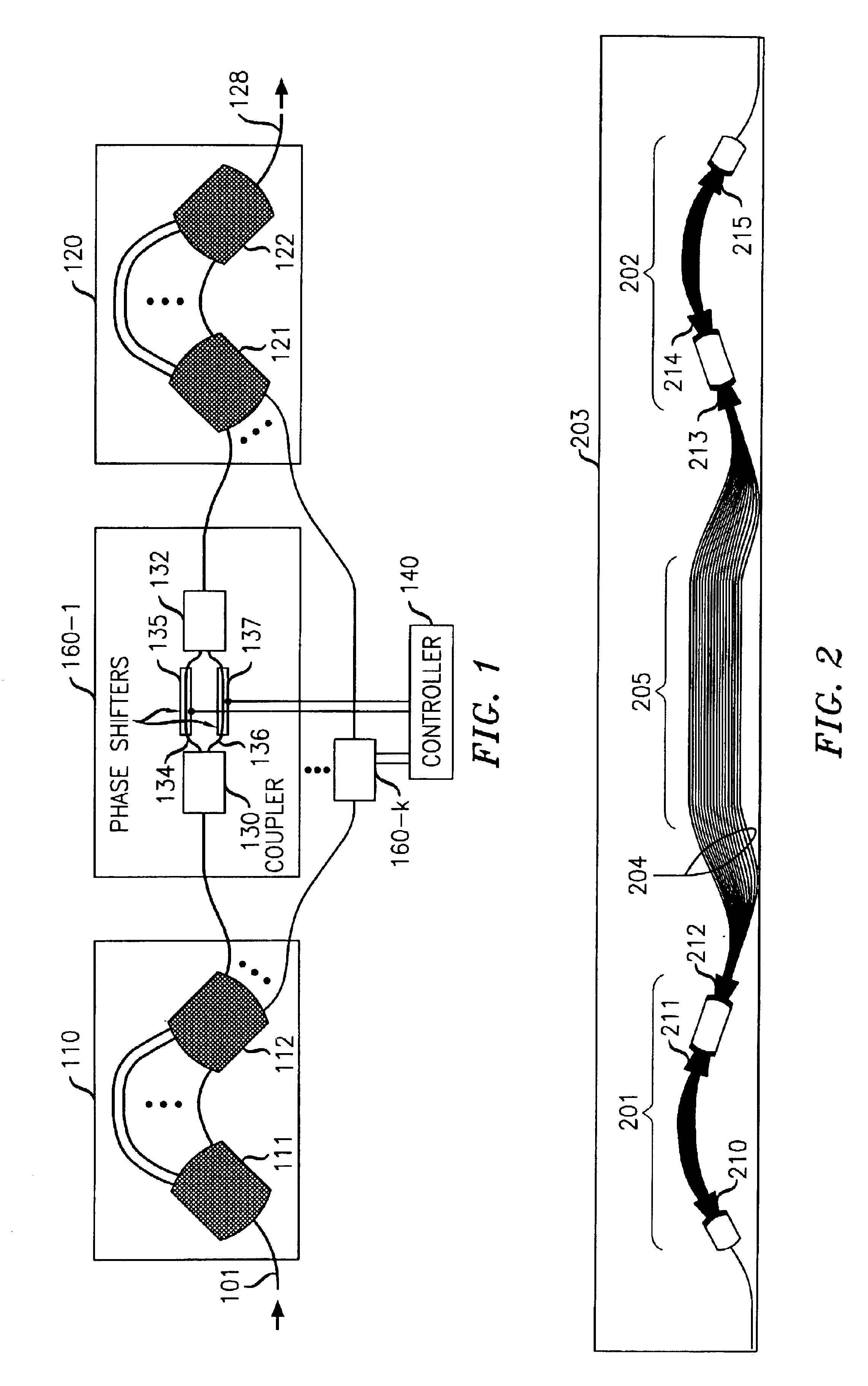
[0015]Referring first to FIG. 1, there is shown a diagram of an arrangement of a DGEF in accordance with the present invention, having a push-pull Mach-Zehnder variable optical attenuator 160-1 to 160-k for each of k wavelength channels. For convenience, only attenuator 160-1 and its associated couplers are shown in detail in FIG. 1. A WDM input signal on input 101 is applied to a first waveguide grating router (WGR) 110 that includes a pair of interconnected star couplers 111 and 112. Preferably, the waveguide grating arm inlets of coupler 112 exactly fill the Brillouin zone of the lens inlets, thereby achieving “perfect spectral sampling”. This can be best accomplished by employing an exponential lens-inlet-center-wavelength spacing so that the sampling is perfect for all lens inlets, and in turn enables the k outputs of star coupler 112 to cumulatively have a ripple-free spectrum. See C. R. Doerr, M. Cappuzzo, E. Laskowski, A. Paunescu, L. Gomez, L. W. Stulz, and J. Gates, “Dynam...


PUM


Abstract

An optical dynamic gain equalization filter (DGEF) comprises a planar arrangement of preferably “perfectly sampled” (or alternatively oversampled) waveguide grating routers (WGR's) connected by individual optical paths each containing a Mach-Zehnder interferometer operated in a push-pull fashion so that a positive phase change in one interferometer arm and a corresponding negative phase change in the other interferometer arm produces a desired change in attenuation while, at the same time, the overall phase of the optical signals after passing through the Mach-Zehnder interferometer is kept constant with respect to the adjacent paths. Alternatively, the above-described arrangement is effectively “cut in half”, and its size effectively also reduced accordingly, using a mirror placed at the midpoint of the device and an appropriate circulator to separate the input and output optical signals.

Description

CROSS-REFERENCE TO RELATED APPLICATION[0001]This application claims priority of Provisional Application Ser. No. 60 / 322,632 which was filed Sep. 17, 2001.TECHNICAL FIELD[0002]The present invention relates generally to optical communications, and more particularly to an arrangement suitable for implementation in integrated optics, for providing dynamic gain equalization on multiple wavelength channels in a wavelength division multiplexed (WDM) optical communication system using push-pull Mach-Zehnder interferometers positioned between two waveguide grating routers that are preferably “perfectly sampled”.BACKGROUND OF THE INVENTION[0003]A dynamic gain equalization filter (DGEF) is a device or arrangement that is useful for controlling wavelength-division multiplexed (WDM) channel powers, especially in ultra-long-haul (>100 km) optical communication systems. Presently, there are fiber-based solutions, for example, as described in H. S. Kim, S. H. Yun, H. K. Kim, N. Park, and B. Y. K...

Claims


Application Information

Patent Timeline
IPC IPC(8): G02B6/34G02B6/12
CPCG02B6/12021G02B2006/12159G02B2006/12038
Inventor DOERR, CHRISTOPHER RICHARD
Owner ALCATEL-LUCENT USA INC
Why Eureka
Try Eureka