Fully integrated self-tuned image rejection downconversion system

a self-tuned, downconversion technology, applied in the direction of amplitude demodulation, line-fault/interference reduction, pulse technique, etc., can solve the problems of low image rejection, i/q mismatch and cross modulation, component external and power consumption, etc., to achieve the effect of low cost and easy integration into a single chip rf+i

Inactive Publication Date: 2005-05-10
INST OF MICROELECTRONICS CHINESE ACAD OF SCI
View PDF13 Cites 80 Cited by
  • Summary
  • Abstract
  • Description
  • Claims
  • Application Information

AI Technical Summary

Benefits of technology

[0022]It is yet a further object of the present invention to provide a system where the I / Q mismatch in the forward path of a receiver can be automatically canceled using the received RF and image signal and where no extra calibration signal is required.
[0023]It is still a further object of the present invention to provide a system which can be fully integrated with low cost analog circuits and which can be easily integrated into a single chip RF+IF receiver.
[0024]These and many other objects have been achieved whereby image rejection is implemented by following a quadrature (I / Q) mixer with a complex filter which is tuned to the desired IF signal passband. The phase mismatch of the I / Q local oscillators and the gain mismatch of the I / Q mixers is eliminated by designing a feedback loop to automatically compensate the matching of the forward I / Q path. In the feedback loop a correlator is used to detect the I / Q mismatches and a gain mismatch estimator is employed to estimate the degree of the mismatches which are needed to be compensated. Further, two variable gain amplifiers (VGAs) are inserted between the I / Q mixer and the complex filter to adjust the gains between I / Q paths so that the phase and amplitude mismatch of the I / Q forward path can be completely eliminated.

Problems solved by technology

This component has to be external and power consumed.
A Zero-IF receiver can be fully integrated and has no problem in image rejection, but it has some disadvantages such as DC offset, I / Q mismatch and cross modulation between RF and LO signal, see T. H. Lee, The Design of CMOS Radio-Frequency Integrated Circuits, U.K.: Cambridge Univ.
The main problem of the low IF receiver is it is not easy to attain the high image rejection with this architecture, i.e. to separate well the desired RF signal from the image signal, see the J. Crols and M. Steyaert, CMOS Wireless Transceiver Design and B. Razavi articles referred to earlier.
Obviously, this filter is very difficult to implement and commonly cannot be integrated.
Unfortunately, the image rejection ratio (IRR) provided by either of the above methods is very sensitive to I / Q mismatch of a low IF receiver, as discussed in the J. Crols and M. Steyaert, “CMOS Wireless Transceiver Design”, B. Razavi, and J. Crols and M. Steyaert, “A single-chip 900 MHz CMOS receiver front-end with a high performance low-IF topology,” articles referred to earlier.
However, it is impossible to attain this perfect matching in current analog IC design process.
The phase mismatch between the LOs and the gain mismatch between the mixers are inevitable.
More importantly, the IRR is very sensitive to these mismatches and the image rejection performance will degrade greatly even with a small amount of mismatches, see J. C. Rudell et al., “A 1.9-GHz wide-band IF double conversion CMOS receiver for cordless telephone applications,”IEEE Journal of Solid-State Circuits, vol.
The matching requirements have put a big challenge to this topology.
High IRR can be attained (50-70 dB) but the cost and complexity of this kind of method is also significantly increased due to the using of DSP.
Additional complexity has been introduced by using baseband signal compensation method.
In the three above cited U.S. Pat. Nos. 4,696,055, 6,137,999, and 5,140,198, to eliminate the phase mismatch between quadrature mixers, adjustable phase shifters have to be used which inevitably increase the complexity of compensation and also decrease the compensation precision.

Method used


Image

  • Fully integrated self-tuned image rejection downconversion system
  • Fully integrated self-tuned image rejection downconversion system
  • Fully integrated self-tuned image rejection downconversion system

Examples


Embodiment Construction

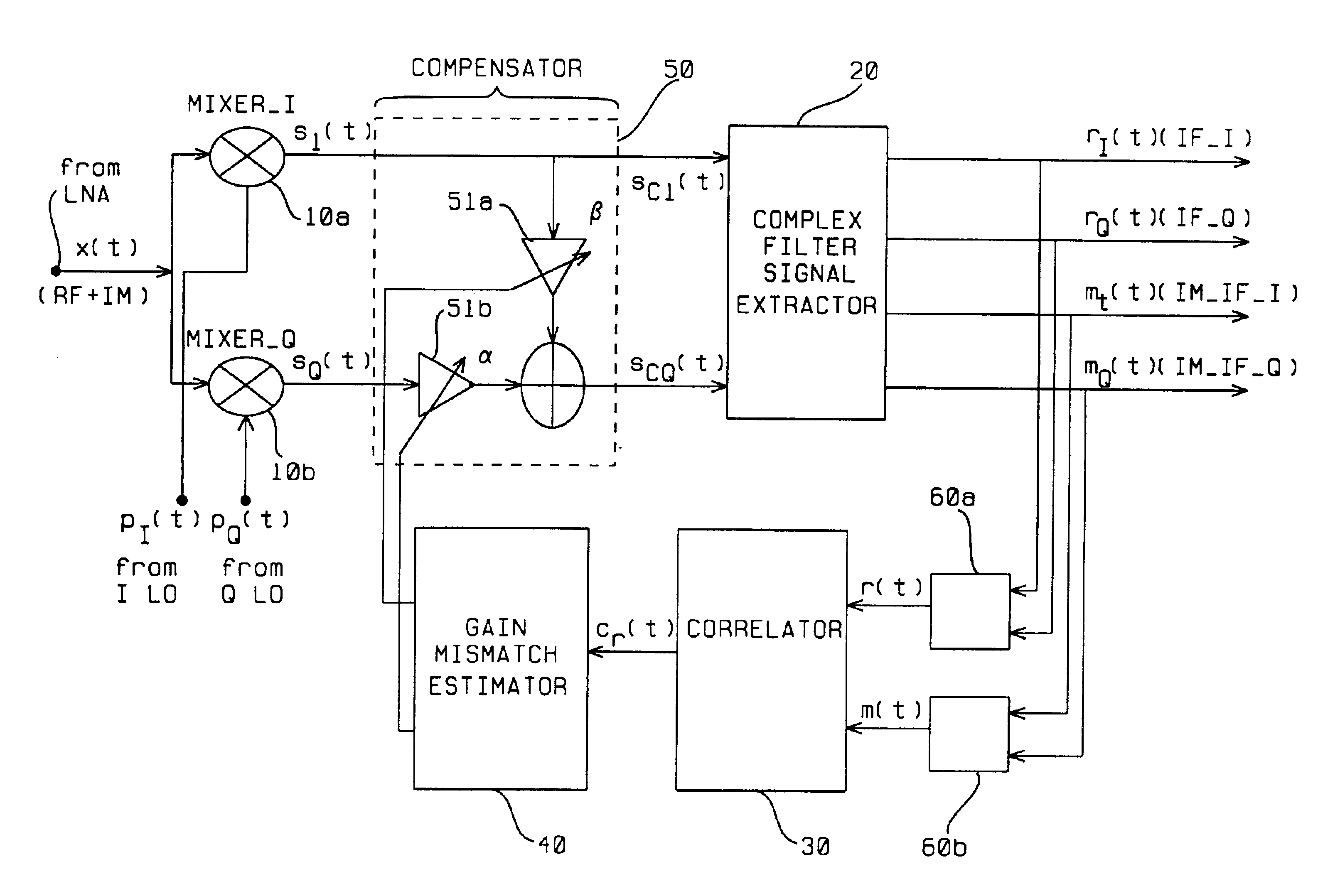
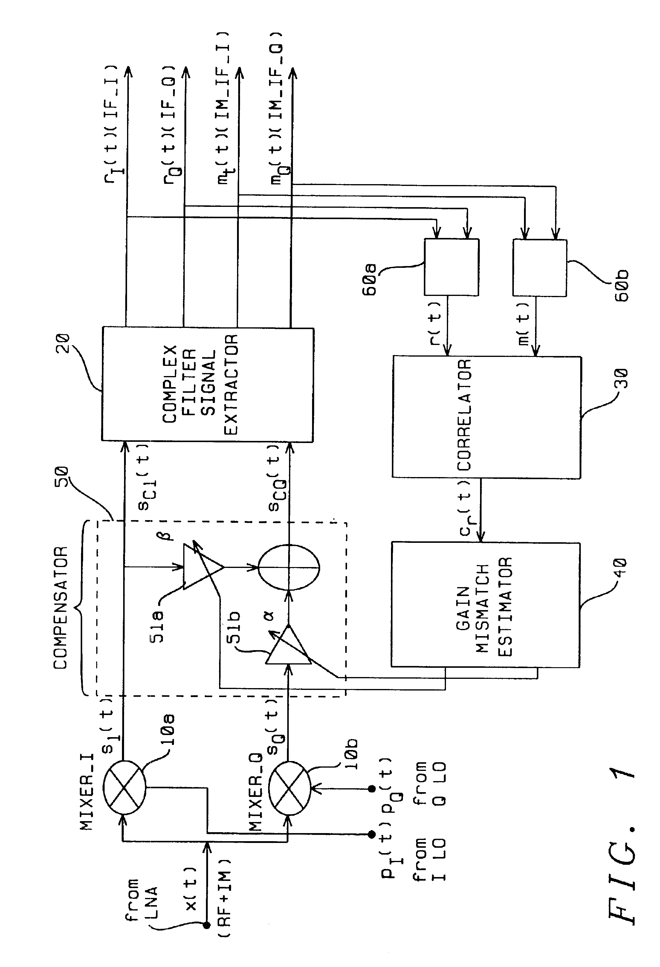
[0030]The proposed architecture is shown in FIG. 1. It includes two paths: the forward path and the feedback path. The forward path is composed of quadrature I and Q (I / Q) mixers 10a, 10b (with two I / Q local oscillators—LOs) and a complex filter signal extractor 20, which is used for frequency downconversion and image rejection. The feedback path is composed of a correlator 30, a gain mismatch estimator 40 and a compensator 50 (with two variable gain amplifiers 51a and 51b) coupled between the I / Q mixers and the, which is used for detecting, estimating and canceling the I / Q mismatches between I / Q mixers and I / Q LOs. Coupled between the complex filter signal extractor and the correlator are blocks 60a and 60b for combining signals from the complex filter signal extractor.

[0031]Referring to FIG. 1, the basic principle of the invention is as follows.

[0032]In the forward path, the input signal x(t), composed of desired RF and image (IM) signal (indicated as RF+IM), comes from a low nois...


PUM


Abstract

A feedback image rejection downconversion system is described, which can be used in low IF receivers with good performance and completely integrated. In the forward path of the system, quadrature mixers and complex filters are used for frequency downconversion and separation of the RF signal from the image signal. In the feedback path, a correlator, a gain mismatch estimator and two VGAs have been used to detect, estimate and compensate the amplitude and phase mismatch between the forward I and Q path signals. The whole system is self-tuned and can operate in both closed and open loop mode. A very high and robust image rejection ratio (over 60 dB) has been achieved.

Description

BACKGROUND OF THE INVENTION[0001]1. Field of the Invention[0002]The invention relates to a downconversion system used in low intermediate frequency (IF) receivers, and more particularly to a downconversion system for low IF receivers with a high image rejection ratio (IRR) of more than 60 dB for use in analog integrated circuits (IC).[0003]2. Description of the Related Art[0004]With the rapid development of wireless communication and IC design technology, wireless transceiver system design and implementation has experienced great evolutions. A very high degree of integration, a low power consumption, and the use of a lower power supply are the goals set for the new development in wireless transceiver design. Although classically the heterodyne multistage intermediate frequency (IF) receiver has good performance in sensitivity and selectivity, it needs a high Q image rejection filter working in high frequency, see J. Crols and M. Steyaert, CMOS Wireless Transceiver Design, Kluwer Aca...

Claims


Application Information

Patent Timeline
Patent Type & Authority Patents(United States)
IPC IPC(8): H03D3/00H04B1/28
CPCH04B1/28H03D3/009
Inventor ZHENG, YUANJIN
Owner INST OF MICROELECTRONICS CHINESE ACAD OF SCI
Why Eureka
Try Eureka