

Assembly method
- Summary
- Abstract
- Description
- Claims
- Application Information
AI Technical Summary
Benefits of technology
Problems solved by technology
Method used
Image

Examples
Embodiment Construction
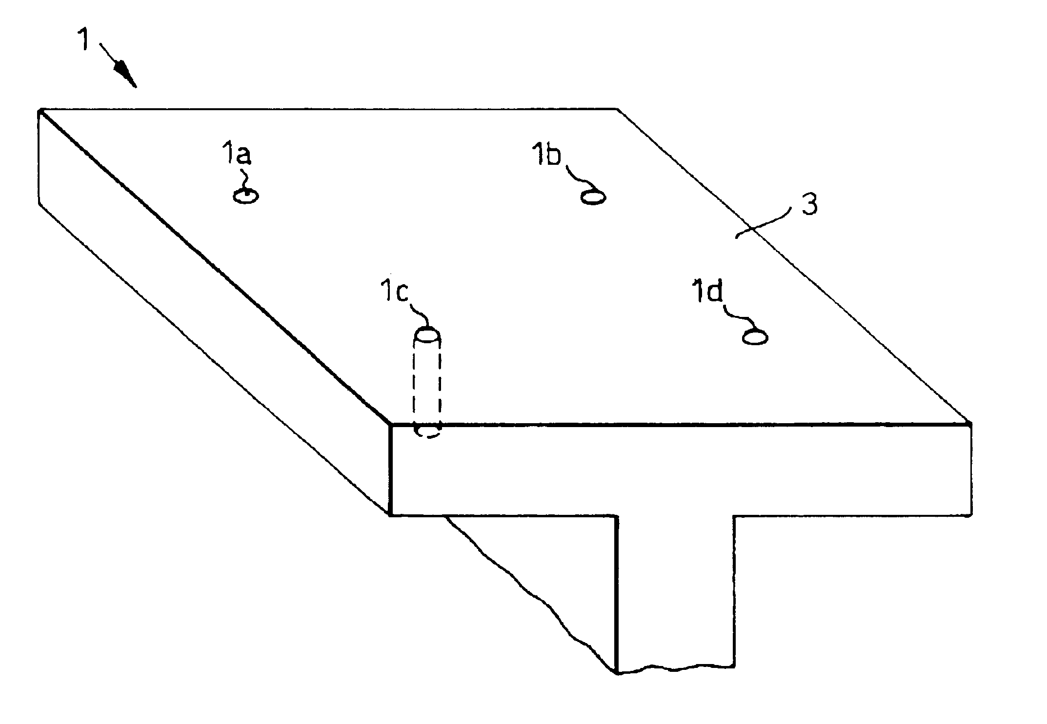
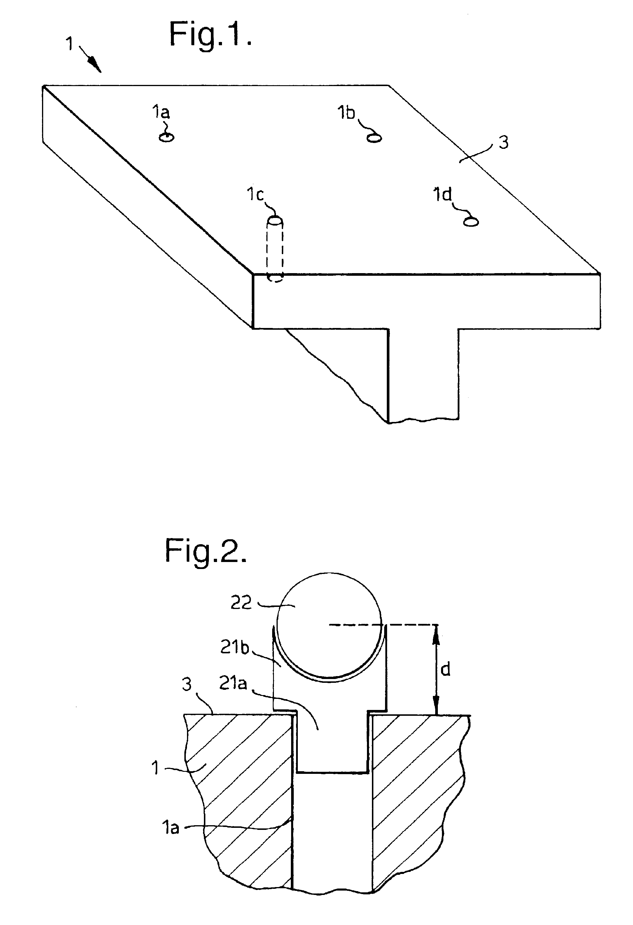
[0029]Referring to FIG. 1, a single rib foot 1 of a rib of an aircraft wing box is illustrated. The upper surface 3 of the rib foot 1 is planar. As can be seen from the figure, four guide holes 1a, 1b, 1c and 1d have been drilled in the rib foot 1 in the desired locations of the final assembly holes, used for securing the wing skin. The guide holes 1a-1d are drilled using a conventional drilling block (not shown) which is used to ensure that the guide holes are drilled perpendicular to the surface 3 of the rib foot 1. The diameter of the guide holes 1a-1d are drilled to a close tolerance. This ensures that their location may be accurately established prior to offering up the wing skin (not shown), as is described below.
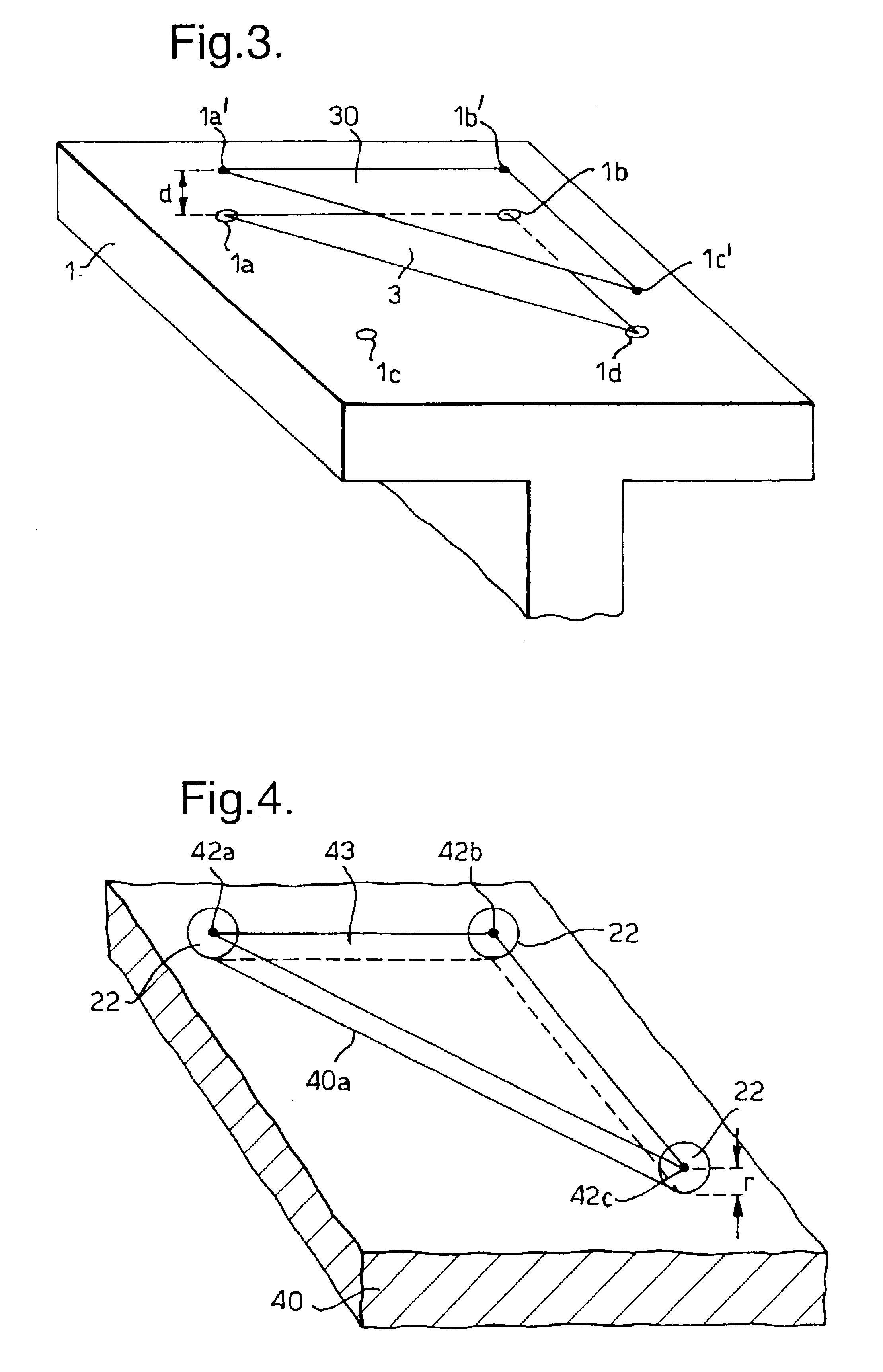
[0030]Establishing the positions of the guide holes 1a-1d is achieved in this embodiment using a laser tracker device and retro-reflector, or corner cube, system. The laser tracker may be the Leica LTD500, which is available with suitable retro-reflectors and suitable...
PUM
 Abstract
Description
Claims
Application Information