Optical communication network and method of remotely managing multiplexers

a technology applied in the field of optical communication network and remote device management, can solve the problems of complex and abstract set of commands or instructions, difficult interpretation/conceptualisation, and the customer cannot rely on unskilled labour to implement changes in the functionality of peripheral equipment, etc., to achieve simplified user interface, greater management flexibility, and simplified interaction through the interface

Inactive Publication Date: 2005-05-10
CIENA
View PDF20 Cites 38 Cited by
  • Summary
  • Abstract
  • Description
  • Claims
  • Application Information

AI Technical Summary

Benefits of technology

[0030]Advantageously, the present invention provides a system in which a standard personal computer (PC) or personal digital assistant (PDA), such as a laptop, having a conventional web-browser application can access a web-based graphic user interface (GUI) to orchestrate functional control of an ADM or the like. Essentially, therefore, the present invention can be controlled to provide a virtual web-server within peripheral (e.g. ADM) equipment, with IP connectivity through the network supporting remote control of the peripheral equipment. Beneficially, the present invention provides a simplified user interface for functional control of remote equipment within an optical domain, with interaction through the interface simplified and generally intuitively based. With the PC otherwise unmodified, no IP-based language understanding needs to be embedded within the PC and hence greater management flexibility is provided to the service operator through their ability to make use of any web-browser supported on a standard PC operating platform. Indeed, with the service provider able to make use of any standard PC, a multiplicity of service terminals are available to the service provider by virtue of their typical prior investment in PCs for office use.
[0031]Beneficially, the present invention avoids the requirement of having to support web-based servers at each peripheral equipment node within a network, with the present invention providing backwards compatibility and future system evolution. Moreover, the present invention limits the cost of manufacture of peripheral equipment having increased management control functionality, with existing equipment up-gradeable through a software release (either in the form of a computer program product, such as a CD ROM) or through software download through the network.
[0032]A further advantage is that the present invention allows use of PC to control the set-up and functionality of either directly connected or remote peripheral equipment within a SONET / SDH environment.

Problems solved by technology

Generally, however, this is not the case and a skilled engineer, visiting a peripheral device, fluent in the program language of the peripheral device is presented with a complex and abstract set of commands or instructions that difficult to interpret / conceptualise.
Presently, therefore, the customer cannot rely on any unskilled labour to implement changes in peripheral equipment functionality and present signalling schemes (through the optical domain and an IP network) are unable to support a graphic user interface (GUI) that would otherwise provide an intuitive / interactive control interface.
In the former respect, the use of internet protocol (IP) language would clearly be preferred but OSI isn't IP compatible, whereas the latter stance is tinged by a practical competent engineer resourcing problem.

Method used


Image

  • Optical communication network and method of remotely managing multiplexers
  • Optical communication network and method of remotely managing multiplexers
  • Optical communication network and method of remotely managing multiplexers

Examples


Embodiment Construction

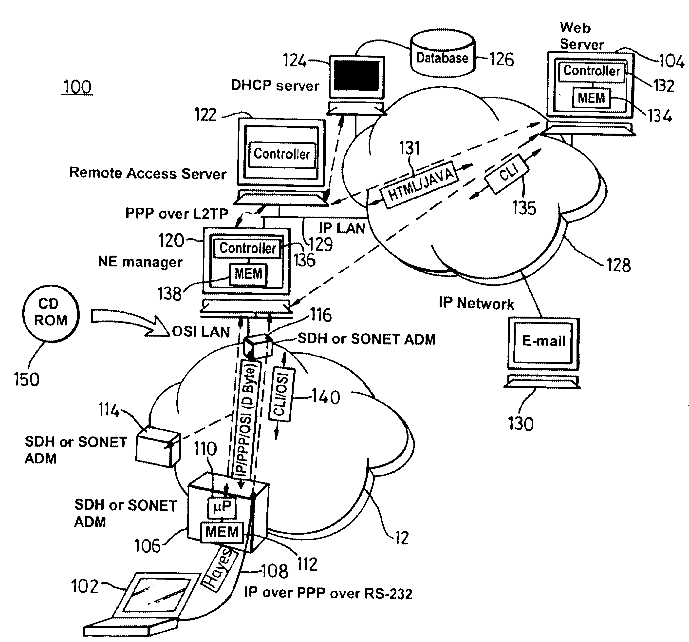
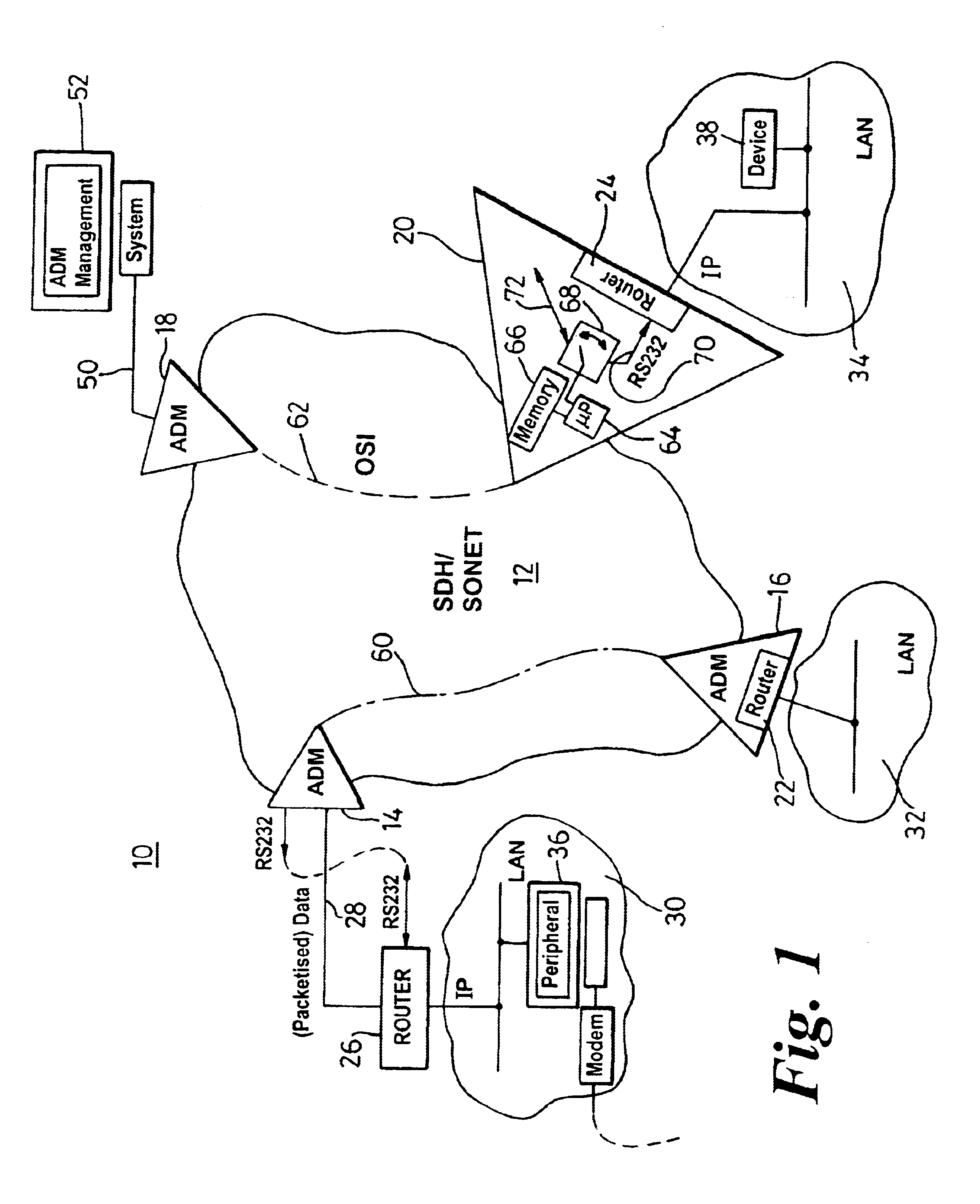
[0039]FIG. 1 is representation of an optical communication network 10. Generally, the optical communication system 10 has a SDH / SONET ring architecture 12 (or functional equivalent) that is accessed by a plurality of ingress and egress points, typically add-drop multiplexers 14-20. The ADMs may contain integral routers 22-24 (such as ADMs 16 and 20), although they may equally be of conventional design where a separate router 26 is coupled to the ADMs through a leased line 28. Local area networks (LANs) 30-34 are generally supported from the ADM or router, with peripheral devices 36-38 having access to the optical communication system 10.

[0040]The optical communication network 10 further includes an ADM 18 providing an interface, via an OSI LAN 50 (for example), to an ADM management system 52.

[0041]FIG. 1 also shows two exemplary connection paths (i.e. allocated communication resources) through the optical communication network 10, namely a data path 60 between two LANs (possibly rep...


PUM


Abstract

To provide a graphic user interface, supported by HTML or Java script, to a personal computer (102) for the control of SONET / SDH network elements (106), an RS-232 port of a PC is used to establish a PPP session to a remote access server, RAS (122). The network element (106) is therefore configured to imitate a modem, and to route PPP packets into its related management system across an optical ring (12). The management system may include an intermediate network manager (120) and a DHCP server (124). Once legitimacy of the PC is established through the IP session, the PC is provided with an IP address to invoke the PC's IP stack. Subsequently, IP is communicated across the PPP session, with the RAS (120) configured to terminate the PPP session and forward IP packets into an IP network (128). IP packets (131), received at a web server (140), are converted into command line interface (CLI) messages 135 and are sent directly to the network manager (120) within an IP packet. The network manager (120) terminated the IP packet and re-packages the CLI messages into an optical carrier format (140) for relay to an addressed network element (106). The addressed network element (106), which is responsive to the CLI messages from a management perspective, then alters its set-up or functionality accordingly. Complex text-based CLI instructions are thus avoided by a field-based engineer through the use of a GUI supported by a PC having web-browser capabilities, with an typical architecture shown in FIG. 2.

Description

BACKGROUND TO THE INVENTION[0001]This invention relates, in general, to an optical communication network and method of remote device management therein, and is particularly, but not exclusively, applicable to the management control and set-up of add-drop multiplexers (and the like) associated with networks that make use of a synchronous optical network (SONET) or synchronous digital hierarchy (SDH) optical communication environment which are managed or maintained by service providers.SUMMARY OF THE PRIOR ART[0002]The expansive bandwidth available in optical networks continues to be reaped and developed in the drive to support every increasing demand for high-speed, high capacity and reliable communication capabilities. Indeed, optical networks provide an ideal transport system for interconnecting remotely separated communication networks, whilst also providing an ability for traffic, both voice and data, to be captured and processed, if desired, an intermediate nodes between the net...

Claims


Application Information

Patent Timeline
Patent Type & Authority Patents(United States)
IPC IPC(8): G06F15/16G06F15/173H04L12/24H04Q11/04
CPCH04L41/0813H04J2203/0058H04L41/22H04L41/0253
Inventor CHRISTIAN, PHILIP J.RAMSDEN, CHRIS
Owner CIENA
Why Eureka
Try Eureka