Method for controlling a spray process

a technology of spraying process and spraying liquid, which is applied in the direction of liquid transfer devices, transportation and packaging, packaging, etc., can solve the problems of difficult to produce the specified coating on subsequent coating runs, high rejection rate, and difficulty in re-spraying coatings, etc., and achieves high quality

Inactive Publication Date: 2005-05-17
SIEMENS ENERGY INC
View PDF6 Cites 8 Cited by
  • Summary
  • Abstract
  • Description
  • Claims
  • Application Information

AI Technical Summary

Benefits of technology

[0007]Aspects of the present invention are based on the determination that the geometrical or spatial relationship between the particle properties of temperature, speed (velocity) and spatial flow rate in a thermal or plasma spray jet, for example, is an important factor affecting the quality and structure of an applied coating. It has been determined by the inventor of the present invention that using these measured in-flight particle properties as a parameter for controlling a spray process allows for producing high quality coatings that may be consistently reproduced.

Problems solved by technology

However, reproducing the specified coating on subsequent coating runs often proves to be difficult even though the same optimized operating parameters are used on restart of the hot spray system.
This may be due to the non-reproducibility of the expected in-flight particle properties on restart.
These results may cause the rejection of non-conforming substrates, stripping the non-conforming coating and re-coating, or relaxing the coating specifications to reduce the rejection rate.
Each of these results increases the cost of production and / or compromises the performance of the coated article.

Method used


Image

  • Method for controlling a spray process
  • Method for controlling a spray process
  • Method for controlling a spray process

Examples


Embodiment Construction

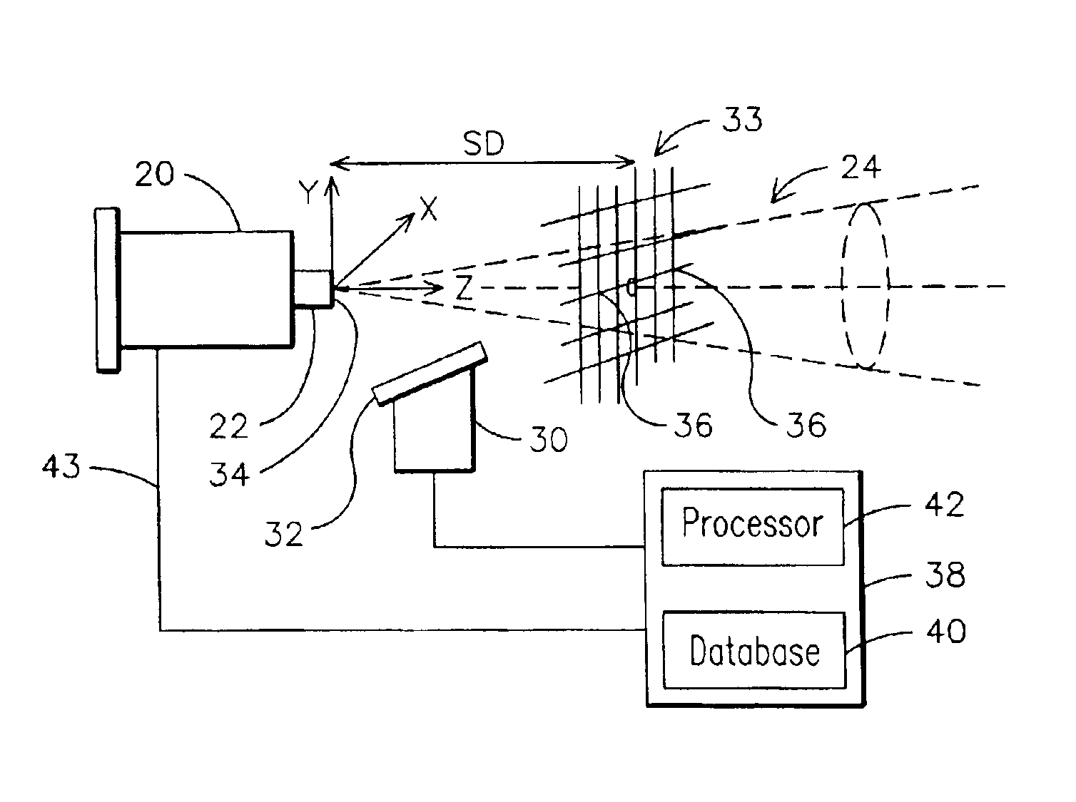
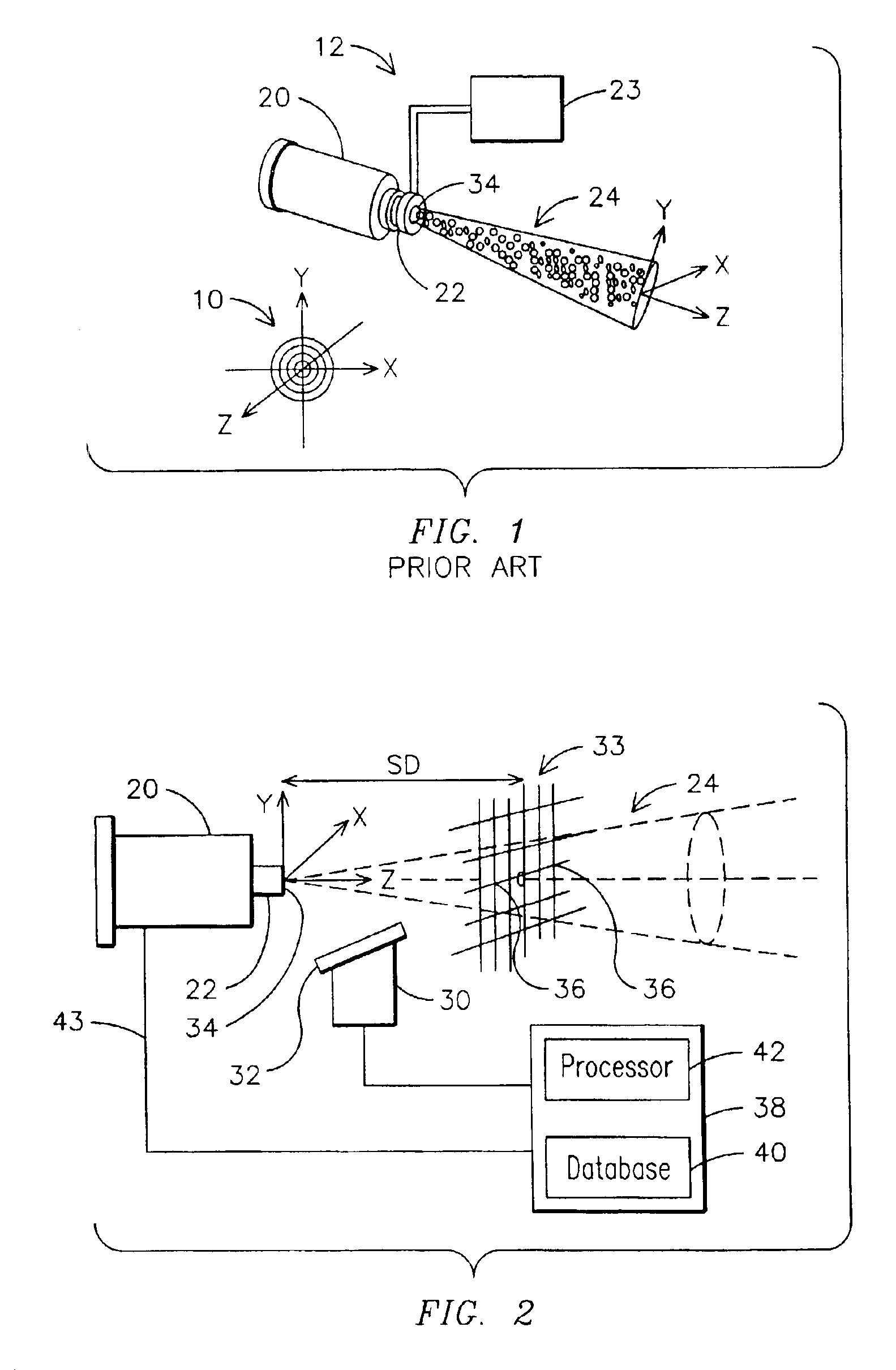
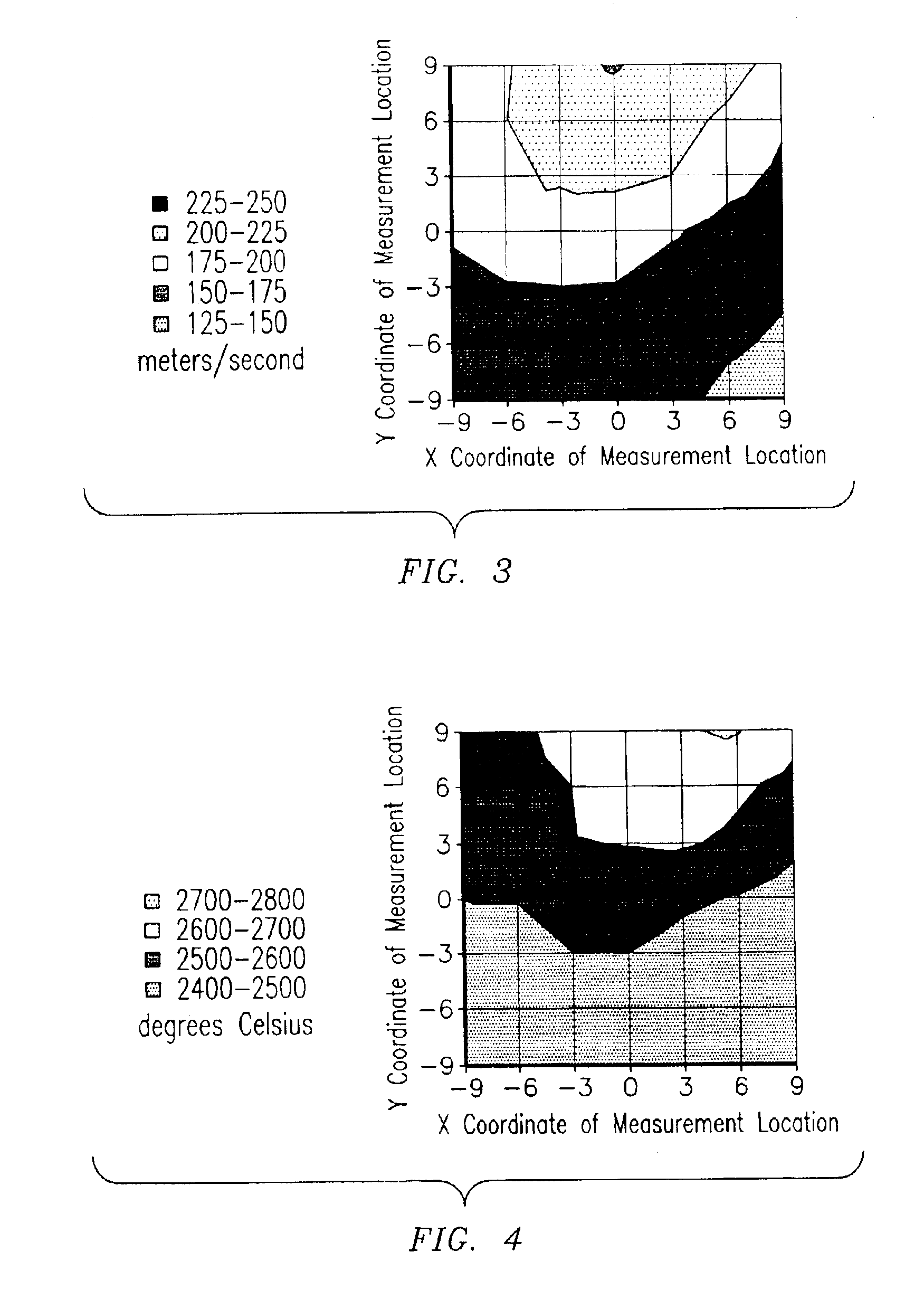
[0017]The hot spray deposition of materials builds up on a substrate as partially and / or fully molten hot particles impact and adhere onto a surface of the substrate. Un-melted hot particles may also adhere to molten material existing on the surface of the substrate. Particles may impact and deform on the surface to become a building block for deposition evolution. The deposition will build up faster in areas of impact having the highest particle flow rate. This is where the largest numbers of such particles per unit area impact the substrate's surface, assuming each particle has the same sticking coefficient or probability.

[0018]In a hot spray system where a powder feedstock is concentrically introduced into an axis-symmetric plasma or combustion gas jet, the iso-property contours of the particles should form concentric circles 10, as shown in FIG. 1, to produce a coating of high quality and structure. In this respect, the region within the gas jet containing particles of maximum p...


PUM

PropertyMeasurementUnit
stand off distanceaaaaaaaaaa
lengthaaaaaaaaaa
areaaaaaaaaaaa

Abstract

A method is provided for controlling a spray process that may include measuring a particle property associated with a spray jet of particles, calculating a centroid for the measured particle property and using the calculated centroid as a control parameter for controlling the spray process. At least one operating parameter associated with the spray process may be adjusted in response to the calculated centroid to change a trajectory of at least a portion of the particles within the spray jet of particles. The operating parameter may be adjusted so that an ensemble of particles having the highest measured temperature and an ensemble of particles having the highest measured velocity and an ensemble of particles having the highest measured flow rate are moved more closely together to create a common region proximate a surface of a substrate to be coated by the spray process. This may be done manually prior to a coating run or continuously during a run using a closed-loop feedback circuit (43) in a computer-controlled (38) spray system.

Description

FIELD OF THE INVENTION[0001]The present invention relates in general to methods for depositing particles on a substrate and, more particularly, to a method for monitoring and controlling a spray process in terms of the properties and flow rates of in-flight particles during the deposition of the particles on a substrate.BACKGROUND OF THE INVENTION[0002]The deposition of particles on articles or substrates may employ various processes including hot spray processes that use combustion or plasma as the heat source. The hot spray of materials or particles on substrates, such as components in a gas turbine for example, may produce multiple surface layers on the substrate having properties that may gradually change and complement the properties of the substrate. The deposited surface layer is intended to protect the substrate during its service against aggressive and hostile environmental attack and extend the component's service life and performance.[0003]Known methods of hot spraying ma...

Claims


Application Information

Patent Timeline
Patent Type & Authority Patents(United States)
IPC IPC(8): C23C4/12
CPCC23C24/04C23C4/12
Inventor SRINIVASAN, VASUDEVAN
Owner SIEMENS ENERGY INC
Why Eureka
Try Eureka