Method for operating a positioning apparatus, and scanning microscope

a positioning apparatus and scanning microscope technology, applied in the direction of converting sensor output, instruments, electric discharge lamps, etc., can solve the problems of sequence then showing defects, overlieing the usable signal, position error, etc., and achieve the effect of higher accuracy

Inactive Publication Date: 2005-05-17
LEICA MICROSYSTEMS CMS GMBH
View PDF3 Cites 10 Cited by
  • Summary
  • Abstract
  • Description
  • Claims
  • Application Information

AI Technical Summary

Benefits of technology

[0016]It is therefore the object of the invention to describe a method for operating a positioning apparatus that allows to achieve a higher accuracy and which allows both the generation of a position signal and tracking of the phase drift.

Problems solved by technology

These interference signals overlie the usable signal and falsify it.
If that position signal is then used in a scanning system to determine the position of a scanned data value, it thus results in a position error.
If, in scanning microscopy, an image sequence is generated using the measured values, that sequence then exhibits defects because of the interference.
The interference on the one hand causes the image sequence to look unsteady, and on the other hand can make it appear distorted.
If image data from the forward and return directions of the scan are used, it may happen that the images of structures that occur in two successive lines can no longer be superimposed.
Thermal and other drift effects cause the delay time between the exciting signal and the position of the galvanometer mirror to change.
This effect must be compensated for manually, in unchangeable fashion.

Method used


Image

  • Method for operating a positioning apparatus, and scanning microscope
  • Method for operating a positioning apparatus, and scanning microscope
  • Method for operating a positioning apparatus, and scanning microscope

Examples


Embodiment Construction

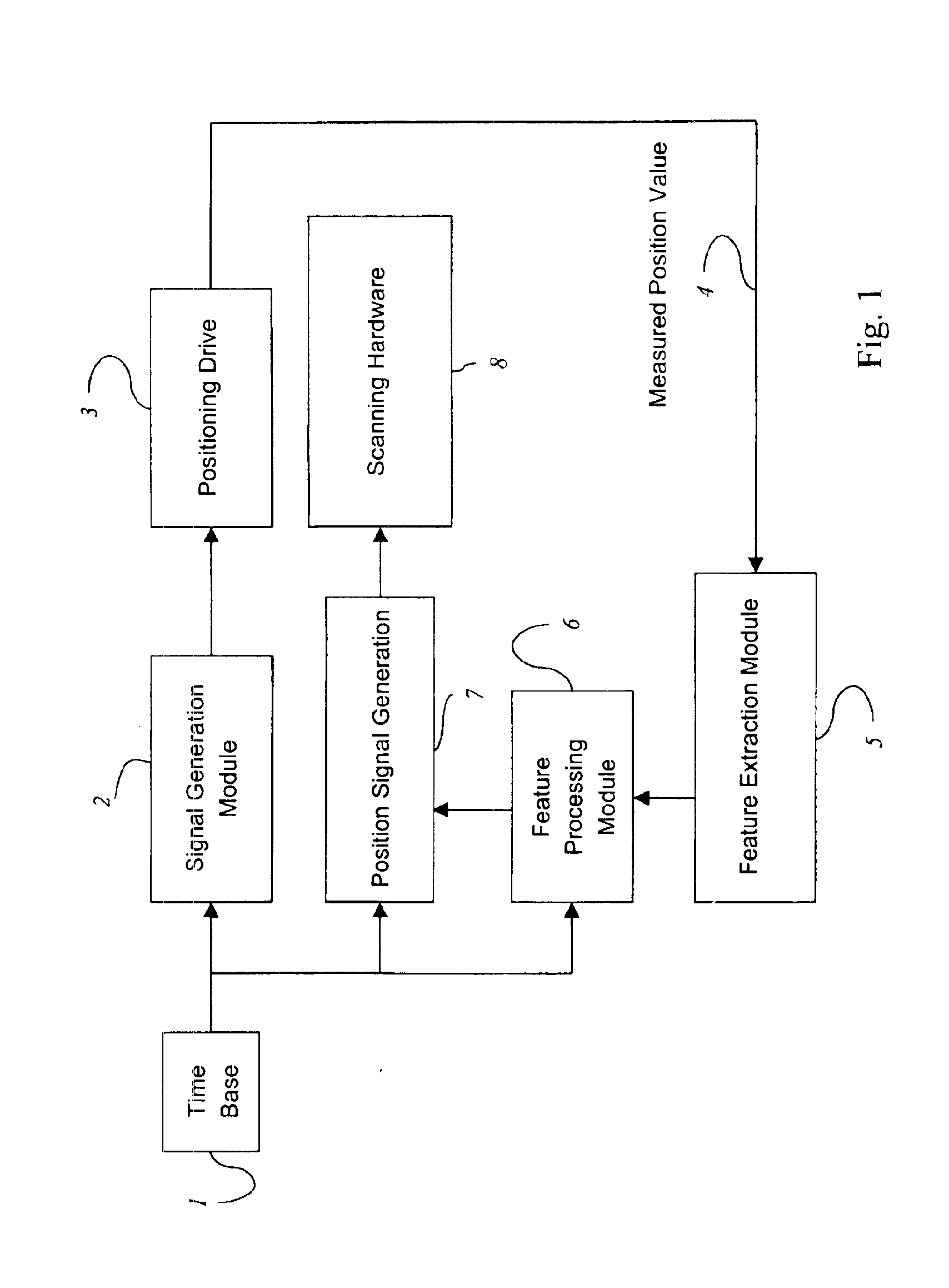
[0047]FIG. 1 shows a flow chart of the method. Time base 1 is configured as a ring counter. The period of one pass corresponds to the desired period of the galvanometer oscillation in the X direction. From this counter value, the position setpoint for a positioning drive 3 is generated in signal generation module 2. Positioning drive 3 contains a position measurement system. Measured position value 4 is conveyed to a feature extraction module 5, in which values characteristic of the position of the positioning drive are extracted. These values are conveyed to feature processing module 6 where, from these data and from the time values generated by time base 1, the correction values necessary for position signal generation 7 are generated. In the module for position signal generation 7, position values are generated from the time values deriving from time base 1 and from the correction values generated by feature processing module 6, and are fed into scanning hardware 8 for further pr...


PUM


Abstract

A method for operating a positioning apparatus that moves a positioning element comprises the steps of: generating a first and at least one further reference signal, the first reference signal corresponding to a first reference position and the further reference signal to a further reference position; generating a first and at least one further estimated value for the present position of the positioning drive; transferring the first reference signal and the estimated value to the positioning apparatus; establishing the first reference position using the positioning apparatus, and measuring the present position and generating a position signal that corresponds to the measured present position; transferring the further reference signal to the positioning apparatus; generating a further estimated value of the positioning drive position; transferring the further estimated value to the positioning apparatus; establishing the further reference position, and measuring a further present position and generating a further position signal that corresponds to the measured further present position; and cyclically repeating the steps at constant time intervals.

Description

CROSS REFERENCE TO RELATED APPLICATIONS[0001]This application claims priority of the German patent application 101 56 235.7 which is incorporated by reference herein.FIELD OF THE INVENTION[0002]The invention concerns a method for operating a positioning apparatus that moves a positioning element.[0003]The invention furthermore concerns a scanning microscope.BACKGROUND OF THE INVENTION[0004]In scanning microscopy, a specimen is illuminated with a light beam in order to observe the reflected or fluorescent light emitted by the specimen. The focus of the illuminating light beam is moved in a specimen plane by means of a controllable beam deflection device, generally by tilting two mirrors; the deflection axes are usually perpendicular to one another, so that one mirror deflects in the X direction and the other in the Y direction. Tilting of the mirrors is brought about, for example, by means of galvanometer positioning elements. The power level of the detected light coming from the spe...

Claims


Application Information

Patent Timeline
Patent Type & Authority Patents(United States)
IPC IPC(8): G02B21/00
CPCG02B21/0036G02B21/0056G02B21/0048
Inventor WIDZGOWSKI, BERND
Owner LEICA MICROSYSTEMS CMS GMBH
Why Eureka
Try Eureka