Permanent magnet dynamo electric machine, and permanent magnet synchronous generator for wind power generation
a permanent magnet dynamo and electric machine technology, applied in the direction of machines/engines, mechanical equipment, mechanical circuit shapes/forms/construction, etc., can solve the problems of eddy current loss of a rotor, eddy current loss caused in the rotor reaches a significant level in some cases, and the current becomes larger
- Summary
- Abstract
- Description
- Claims
- Application Information
AI Technical Summary
Problems solved by technology
Method used
Image
Examples
embodiment 1
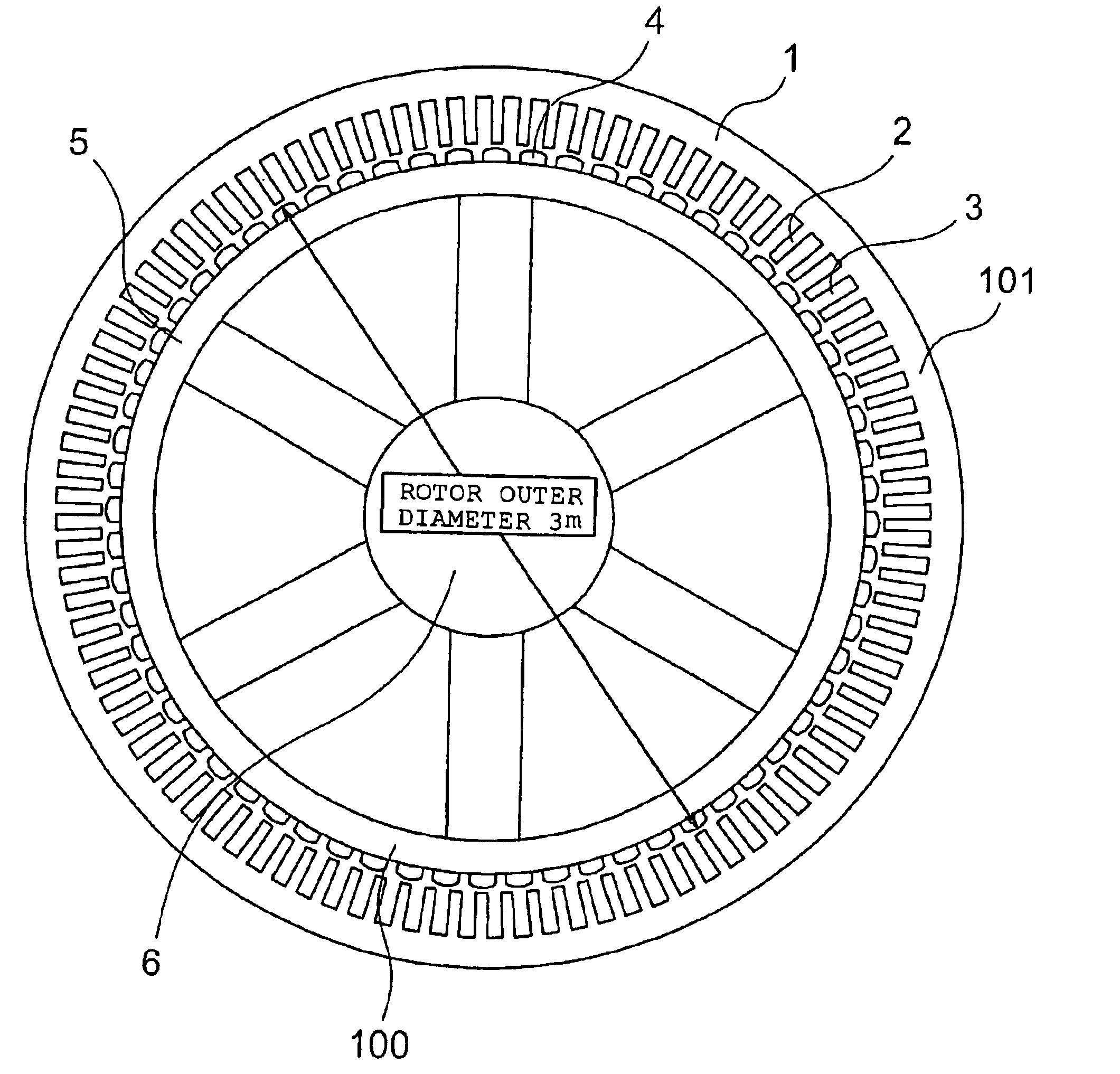
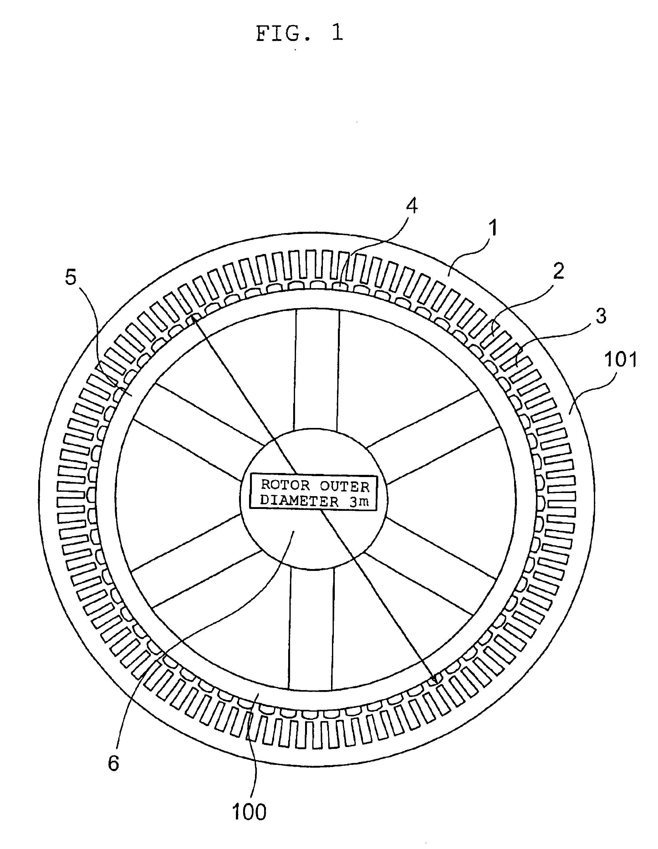
[0033]An example of an embodiment mode 1 of the present invention is shown in FIG. 1. FIG. 1 is a permanent magnet type synchronous generator of an inner rotor type. That is, in FIG. 1, a stator 101 is positioned outside a rotor 100. In FIG. 1, reference numeral 1 designates a stator iron core constituting the stator 101, reference numeral 2 designates a plurality of teeth provided in the stator iron core 1, reference numeral 3 designates a slot as a recess portion which is formed between the adjacent teeth 2, reference numeral 4 designates a plurality of permanent magnets provided in the rotor 100, reference numeral 5 designates an integral type massive rotor yoke to which the permanent magnets 4 are attached at equal intervals, and reference numeral 6 designates a rotation axis of the rotor 100.
[0034]As shown in FIG. 1, a rotor outer diameter is 3 m, the number of permanent magnets 4 provided in the rotor 100 (i.e., the number of rotor magnetic poles) is 64, and each of the number...
embodiment 2
[0054]In this embodiment mode, similarly to the permanent magnet type dynamo electric machine shown in the embodiment mode 1, the description will hereinbelow be given with respect to an example in which such a construction as to meet Expression (19) shown in the above-mentioned embodiment 1 is applied to a permanent magnet type synchronous generator for wind power generation including a rotor having a plurality of magnetic poles composed of permanent magnets, and a stator having armature windings wound around the magnetic poles. Schematic diagrams of a wind power generation system are shown in FIG. 11 and FIG. 12. In these figures, reference numeral 10 designates a tower as a pole brace of the wind power generation system, and reference numeral 11 designates a nacelle provided on the tower 10. In the inside of the nacelle 11, in an example of FIG. 11, a generator 12 and an accelerating gear 13 are provided, while in an example of FIG. 12, only the generator 12 is provided. Referenc...
embodiment 3
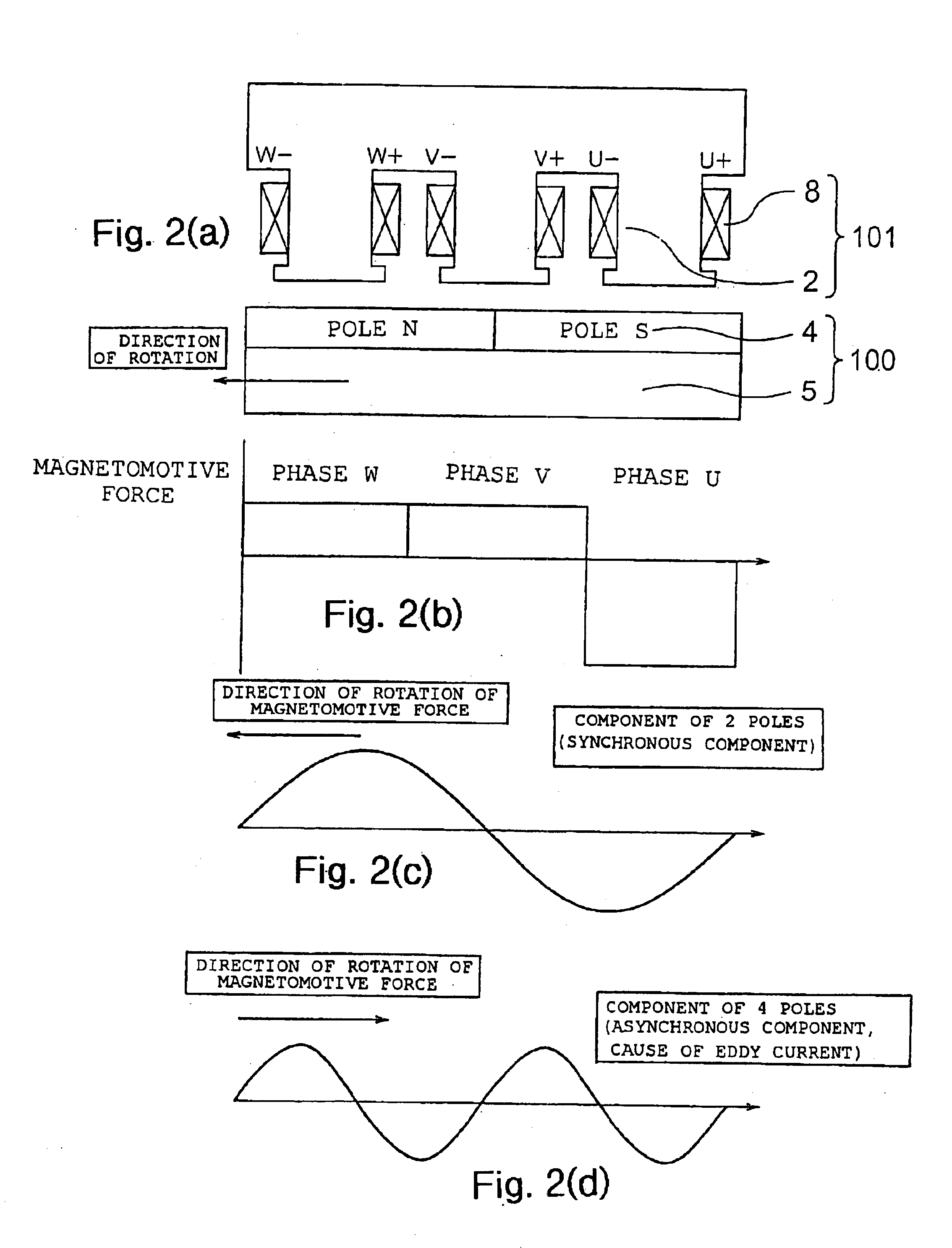
[0058]As has been described so far, in the large permanent magnet type generator or motor in which the rotor is of the concentrated wiring, if the number P of pole pairs and the spatial harmonic order N of the magnetomotive force to be the cause of an eddy current are not suitably selected, then an eddy current loss of the rotor may be remarkably increased in some cases. In other words, if the number P of pole pairs and the number S of slots are not suitably selected, then there is a fear of calorification due to the eddy current, and reduction of the efficiency. On the other hand, various combinations are considered for the number 2P of poles and the number S of slots of the dynamo electric machine with the concentrated winding. As the combination which is often used, there are the combinations of 2P:S=4:3, 10:9, 8:9, 10:12, 2:3 and the like. Here, designs are considered of permanent magnet type synchronous generators having the same output and each having a rotor outer diameter of...
PUM
 Abstract
Description
Claims
Application Information
 - R&D
- Intellectual Property
- Life Sciences
- Materials
- Tech Scout
- Unparalleled Data Quality
- Higher Quality Content
- 60% Fewer Hallucinations
Browse by: Latest US Patents, China's latest patents, Technical Efficacy Thesaurus, Application Domain, Technology Topic, Popular Technical Reports.
© 2025 PatSnap. All rights reserved.Legal|Privacy policy|Modern Slavery Act Transparency Statement|Sitemap|About US| Contact US: help@patsnap.com


