Method and system for uploading and downloading engine control data

a technology of engine control and data uploading, applied in the field of engine control, can solve the problems of software loaders not operating, time-consuming approaches, and logistical problems,

Inactive Publication Date: 2005-05-17
GENERAL ELECTRIC CO
View PDF6 Cites 61 Cited by
  • Summary
  • Abstract
  • Description
  • Claims
  • Application Information

AI Technical Summary

Benefits of technology

[0009]The above-mentioned need is met by the present invention, which provides a method and system for transmitting engine control data to or from the engine control unit of an engine. The system includes a local communication unit capable of establishing a wireless communication link with a remote communication unit and means for transferring data between the local communication unit and the engine control unit. In operation, a wireless communication link is established between the local communication unit and the remote communication unit. Engine control data is transferred between the local communication unit and the engine control unit and transmitted between the local communication unit and the remote communication unit via the wireless communication link.
[0010]The present invention and its advantages over the prior art will be more readily understood upon reading the following detailed description and the appended claims with reference to the accompanying drawings.

Problems solved by technology

There are logistical problems associated with both approaches.
This approach can be time consuming because a stepladder is often needed to connect cables to the ECU.
Furthermore, not all aircraft have an aircraft software loader installed, and of those that do, not all of the aircraft software loaders are linked to the ECU.
Both approaches suffer from the fact that software loaders can fail to operate under extreme temperature conditions due to disk drive limitations.

Method used


Image

  • Method and system for uploading and downloading engine control data
  • Method and system for uploading and downloading engine control data
  • Method and system for uploading and downloading engine control data

Examples


Embodiment Construction

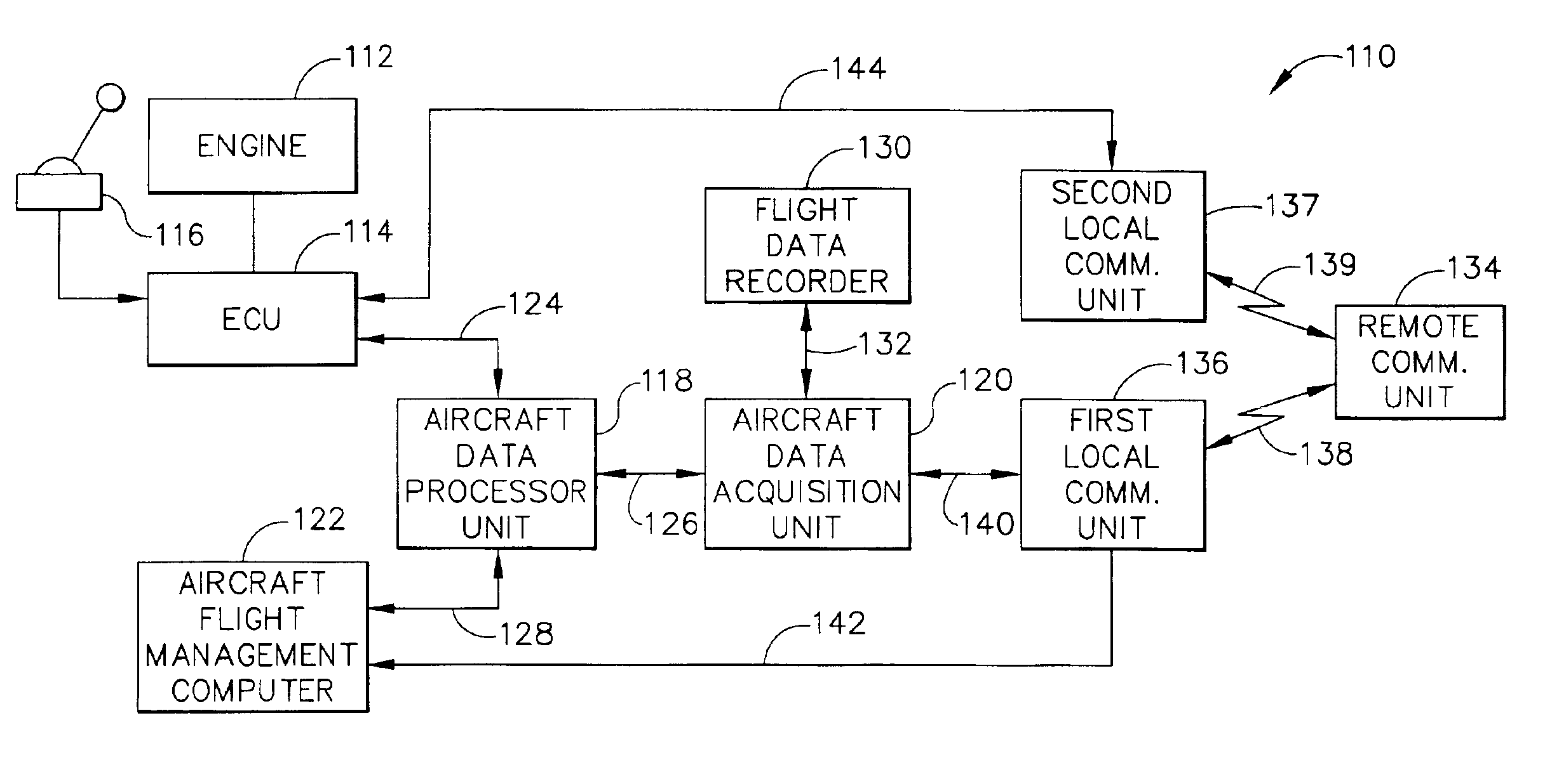
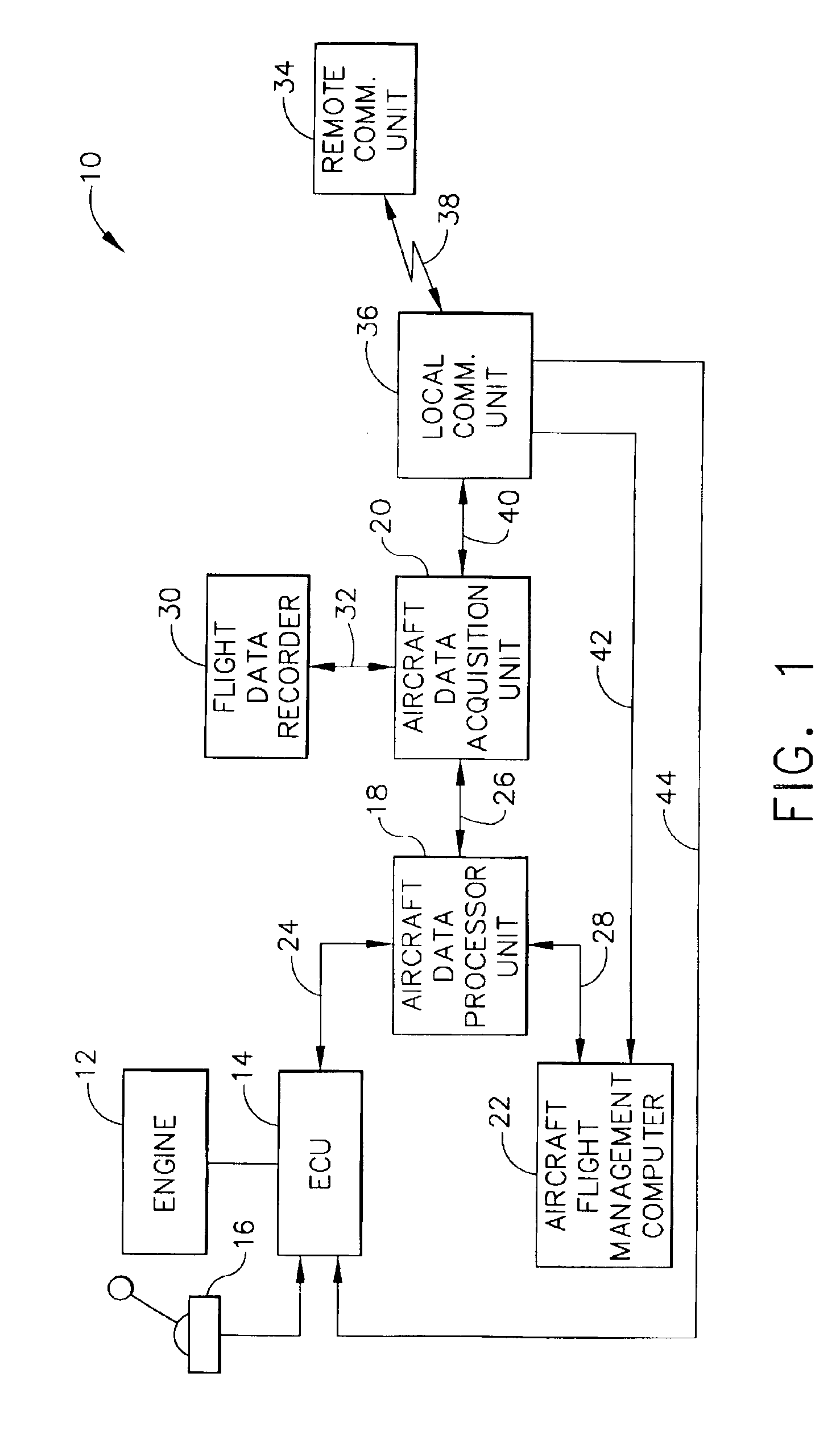
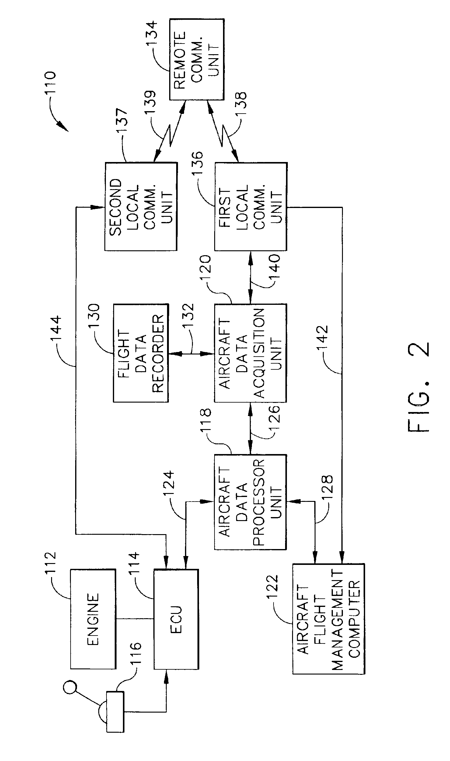
[0014]Referring to the drawings wherein identical reference numerals denote the same elements throughout the various views, FIG. 1 shows a block diagram of a system 10 for transmitting (i.e., downloading and / or uploading) engine control data in connection with the operation of an engine 12. The engine 12 can be any type of engine such as a gas turbine engine, a pulse detonation engine or the like. As used herein, the term “engine control data” refers to any data that can be stored in, and transmitted to or from, an electronic control unit. Generally, an airline operator or data service provider would utilize the system 10 to direct data transmissions from a ground-based service center. The engine 12 is used to power a craft such as an aircraft or a marine vessel. For purposes of illustration only, the engine 12 is described in connection with an aircraft. However, it should be noted that the system 10 is applicable to other applications of engines, including marine and industrial ap...


PUM


Abstract

A method and system for transmitting engine control data to or from the engine control unit of an engine. The system includes a local communication unit capable of establishing a wireless communication link with a remote communication unit and a link for transferring data between the local communication unit and the engine control unit. In operation, a wireless communication link is established between the local communication unit and the remote communication unit. Engine control data is transferred between the local communication unit and the engine control unit and transmitted between the local communication unit and the remote communication unit via the wireless communication link.

Description

BACKGROUND OF THE INVENTION[0001]This invention relates generally to engine controls and more particularly to transmitting engine control data.[0002]Gas turbine engines are used for a wide variety of aeronautical, marine and industrial applications. Generally, a gas turbine engine includes a compressor that provides pressurized air to a combustor, wherein the air is mixed with fuel and the mixture is ignited for generating hot combustion gases. These gases flow downstream to a turbine section that extracts energy therefrom to drive the compressor and provide useful work.[0003]Pulse detonation engines have also been proposed for many such applications. A pulse detonation engine uses an intermittent combustion process to create a temperature and pressure rise by detonating a flammable mixture. A pulse detonation engine is typically a tube of a specified length that is open at the aft end and includes some sort of valve device at the front end to keep the detonation process from travel...

Claims


Application Information

Patent Timeline
Patent Type & Authority Patents(United States)
IPC IPC(8): F02C9/00F02D45/00F02C9/28F02D29/02
CPCF02C9/00
Inventor BUTZ, MARK GERARDSCHUSTER, RICHARD FRANCISDEPEW, KIMBERLY ANNE
Owner GENERAL ELECTRIC CO
Why Eureka
Try Eureka