Optical synchronization system

a technology of optical synchronization and optical synchronization, applied in the direction of synchronization signal speed/phase control, multiplex communication, wireless commuication services, etc., can solve the problems of significant capital expense, severely limit the size of offices that may be served, and difficult management and routing of timing cables, so as to reduce the number of links required, ensure the survivability of a portion of the active link, and avoid the cost and decrease of the reliability of fully redundant active optical links

Inactive Publication Date: 2005-05-17
LUCENT TECH INC
View PDF17 Cites 61 Cited by
  • Summary
  • Abstract
  • Description
  • Claims
  • Application Information

AI Technical Summary

Benefits of technology

[0007]The series-connected arrangement employs both active and passive optical paths. The active path provides clock signal regeneration and performance monitoring functions, while the passive path is more reliable, that is, the passive path is not susceptible to power failures or other failures that may affect the active path, for example. In an illustrative embodiment, the active and passive paths of a daisy-chained group of synchronization distribution units are cross-coupled. That is, the passive optical output of one synchronization distribution unit is connected to the active optical input of a downstream synchronization distribution unit and the active optical output of the synchronization distribution unit is connected to the passive optical input of the downstream synchronization distribution unit. This cross-coupling permits the system to use a passive link to “loop-around” a failed active link, thereby ensuring the survivability of a portion of the active link while avoiding the cost and decreased reliability of fully redundant active optical links. Additionally, since a synchronization distribution unit would receive synchronization signals from two different upstream synchronization distribution units, the passive link being supplied by the active elements within the immediately preceding synchronization distribution unit and the active link being supplied by the active elements from the preceding synchronization distribution unit preceding that one.
[0008]A synchronization system in accordance with the principles of the present invention distributes synchronization signals from a central synchronizing management unit through one or more synchronization distribution units to network elements (network elements) within an office that require external synchronization. In an illustrative embodiment synchronization and management signals are carried over optical links between a central synchronizing management unit and each synchronization distribution unit, and between each synchronization distribution unit and each network element. The distributed architecture of the present invention, an architecture that distributes synchronization and management signals to synchronization distribution units which, in turn distribute signals to network elements, reduces the number of links required for the distribution of these signals. That is, each synchroniz

Problems solved by technology

In larger offices, offices that employ in the tens of network elements or more, the management and routing of the timing cables can prove to be challenging.
Such length restrictions may severely limit the size of office that may be served by such a conventional synchronization system, with larger offices requiring the addition of another BITS clock.
Not only is there a significant capital expense associated with the addition of a BITS clock, the increased maintenance costs can also be significant.
Additionally, noise and crosstalk electromagnetically induced on the cables can seriously degrade the per

Method used


Image

  • Optical synchronization system
  • Optical synchronization system
  • Optical synchronization system

Examples


Embodiment Construction

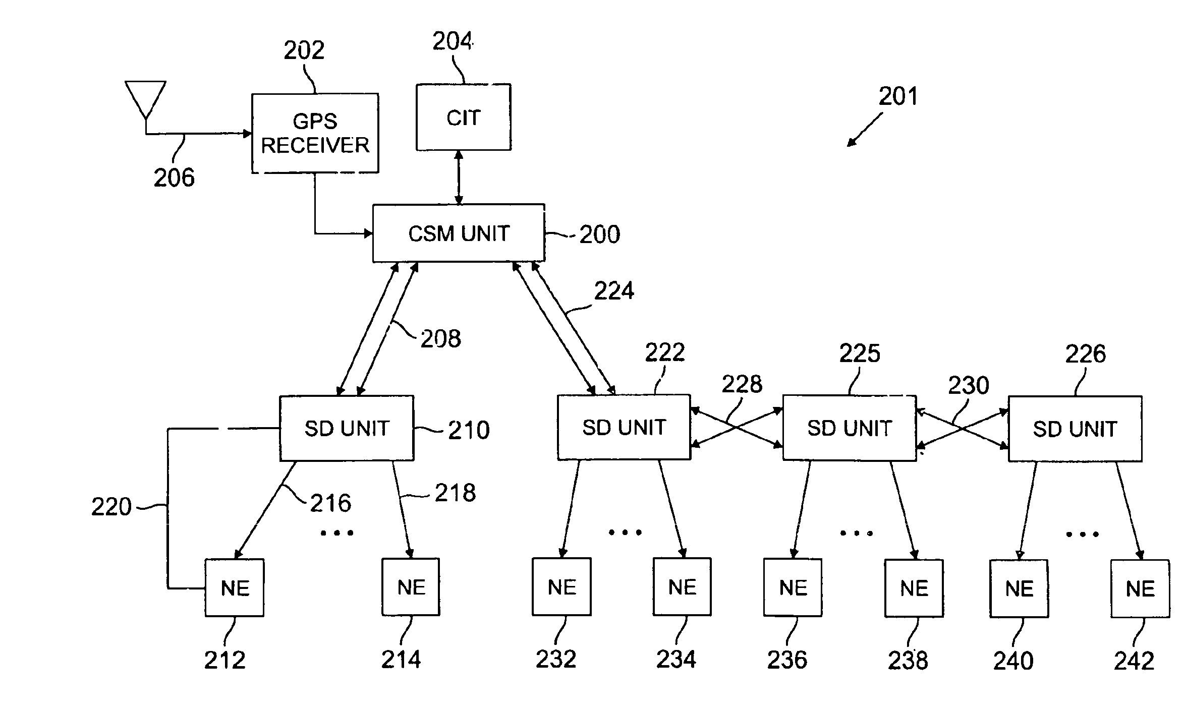
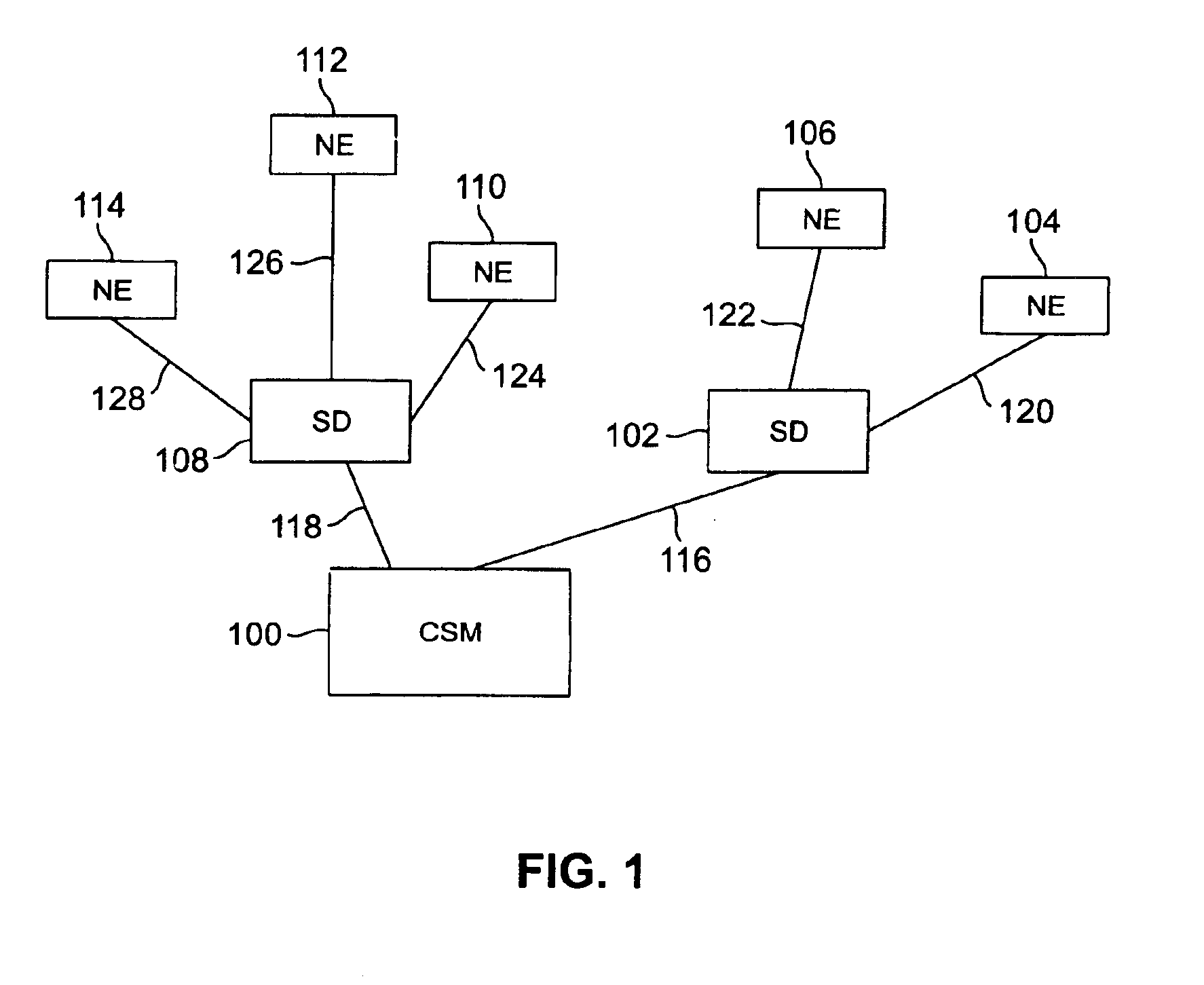
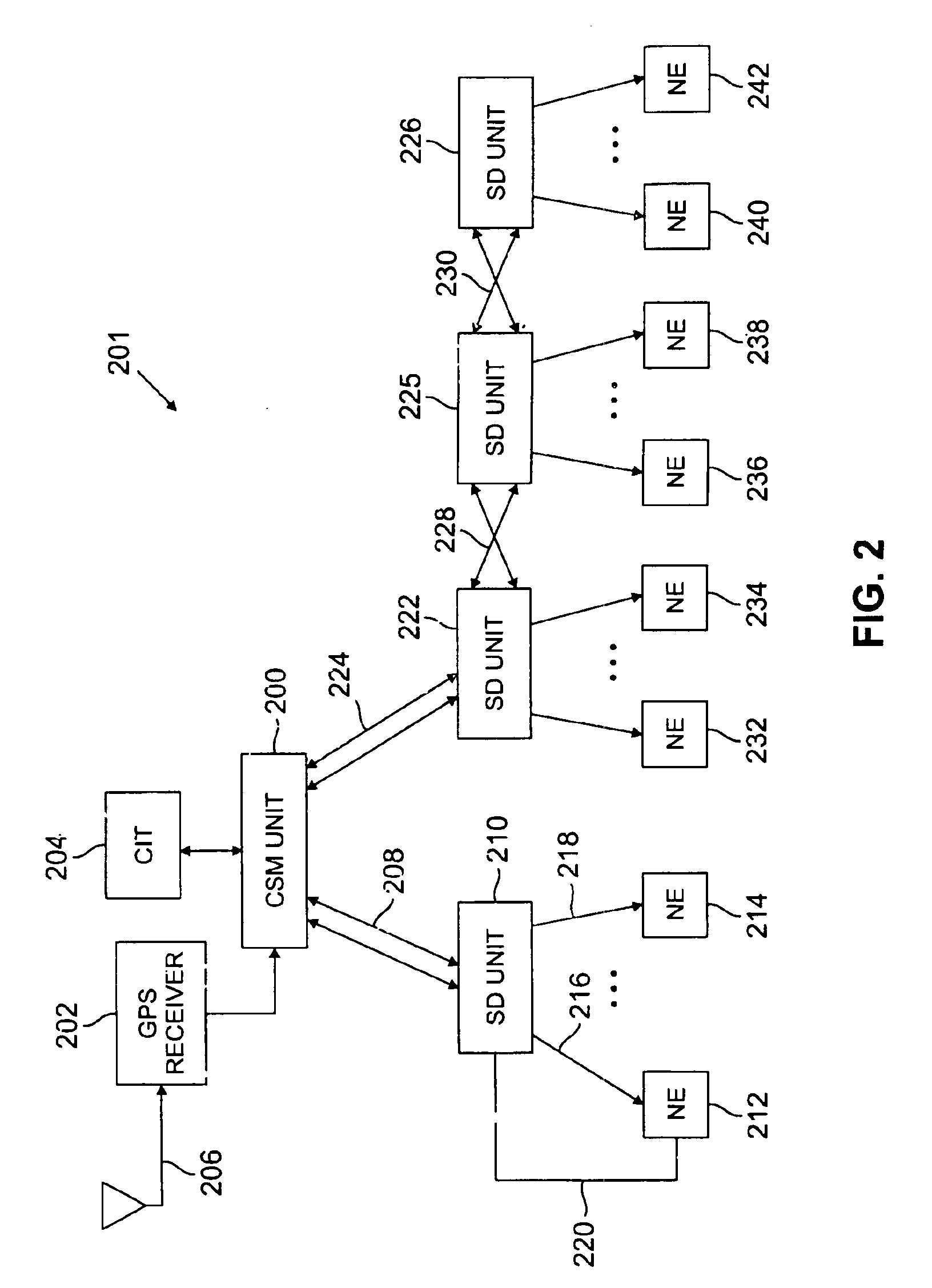
[0015]A synchronization system in accordance with the principles of the present invention distributes synchronization signals from a central synchronizing management unit through one or more synchronization distribution units to network elements within an office that require external synchronization. In an illustrative embodiment synchronization and management signals are carried over optical links between a central synchronizing management unit and each synchronization distribution unit, and between each synchronization distribution unit and each network element. The distributed architecture of the present invention, an architecture that distributes synchronization and management signals to synchronization distribution units which, in turn, distribute signals to network elements, reduces the number of links required for the distribution of these signals. That is, each synchronization distribution unit acts as a concentrator, preferably communicating with a plurality of network elem...


PUM


Abstract

A synchronization system in accordance with the principles of the invention includes a central synchronizing management unit, at least one synchronization distribution unit, and at least one network element. Each synchronization distribution unit receives synchronization and management information from the central synchronization management unit. This information may be transmitted directly from the central synchronization management unit, or it may be transmitted though another synchronization distribution unit in a group of a daisy-chained synchronization distribution units. The daisy-chained arrangement employs both active and passive optical paths. The central synchronizing management unit may query any synchronization distribution unit within the system to obtain performance statistics. Additionally, the central synchronizing management unit may detect faults within the system by setting performance monitoring thresholds and interrogating a synchronization distribution unit to determine whether a threshold has been exceeded. The synchronization distribution units are physically located in close proximity to the network elements they serve. Additionally, the management and synchronization information exchanged between the central synchronization unit and a synchronization distribution unit is carried over a bidirectional optical link.

Description

FIELD OF THE INVENTION[0001]The invention relates to synchronization systems and, more particularly, to synchronization systems for the telephone office environment.BACKGROUND OF THE INVENTION[0002]Synchronization systems are widely employed within telephone offices, for example, to distribute synchronization signals to various digital circuit elements that employ the synchronization signals in the timing, transmission, reception, and routing of signals. A typical office, such as a telephone central office, includes a central synchronization generator, such as a building integrated timing supply (BITS) clock, which generates and distributes the synchronization, or clock, signals throughout the office to individual network elements within the office. Conventional clock distribution systems often employ DS1 or composite clock timing signals which operate, respectively, at 1.544 Mb / s and 8 / 64 kb / s. In small offices, this mode of timing distribution is both economical and adequate. In l...

Claims


Application Information

Patent Timeline
IPC IPC(8): H04B10/00H04B10/272H04L7/033
CPCH04L7/033H04B10/272
Inventor BEDROSIAN, PAUL STEPHAN
Owner LUCENT TECH INC
Why Eureka
Try Eureka