Angular velocity detection device

a detection device and angular velocity technology, applied in the direction of instruments, digital computer details, navigation instruments, etc., can solve the problems of sensitivity coefficient k that cannot allow the actual angular velocity sub>y /sub>of the sensitivity coefficient k cannot allow the actual angular velocity sub>y /sub> of the vehicle to be detected with high accuracy, and the sensitivity coefficient k cannot be adjusted relative to

Active Publication Date: 2005-05-17
PIONEER CORP
View PDF7 Cites 16 Cited by
  • Summary
  • Abstract
  • Description
  • Claims
  • Application Information

AI Technical Summary

Benefits of technology

[0020]The present invention was developed in view of the aforementioned conventional problems. It is therefore an object of the present invention to provide an angular velocity detection device which is capable of preventing degradation in detection accuracy caused by the detection axis of the angular velocity sensor being tilted thereby allowing angular velocities to be sensed with high accuracy even when data such as the known orientation or positioned location provided by the GPS cannot be used, the device being designed to improve the accuracy of the orientation obtained by integrating an angular velocity thereby determining an accurate current position.

Problems solved by technology

This causes the aforementioned sensitivity coefficient K to have an error with respect to the sensor output ωgyro, so that the multiplication of the sensor output ωgyro (i.e., ωq) of the angular velocity sensor by the sensitivity coefficient K would not allow the actual angular velocity ωy of the vehicle to be detected with high accuracy.
Thus, the multiplication of the sensor output ωgyro (i.e., ωq) of the angular velocity sensor by the sensitivity coefficient K would not allow the actual angular velocity ωy of the vehicle to be detected with high accuracy.
In this case, the orientation of the detection axis is tilted at a total angle (θset+θinc) of the setting angle θset and the angle of inclination θinc relative to the vertical direction P. This causes the error in the sensitivity coefficient K relative to the sensor output ωgyro to become more noticeable, so that the multiplication of the sensor output ωgyro of the angular velocity sensor by the sensitivity coefficient K would not allow the actual angular velocity ωy of the vehicle to be detected with high accuracy (See Japanese Patent Application Laid-Open No.
While the vehicle is traveling where GPS signals cannot be received, it is impossible to make the compensation in accordance with the absolute orientation and the positioned location provided by the GPS position information.
However, under the circumstances in which data such as the aforementioned known orientation or positioned location cannot be used, errors in the orientation obtained by integrating angular velocities are accumulated, thus resulting in a lowered degree of orientation accuracy and location accuracy of the current position.
In this case, errors in the actual angular velocity ωy of the vehicle are accumulated, thus resulting in a lowered degree of orientation accuracy and location accuracy of the current position as well.
In this case, when the vehicle makes a turn while running along an inclined road, the error of the actual angular velocity ωy of the vehicle is further increased, thus resulting in a lowered degree of orientation accuracy and location accuracy of the current position as well.
This makes it difficult to sense the actual angular velocity ωy of the vehicle with high accuracy and causes errors to be accumulated in the orientation obtained by integrating an angular velocity, resulting in a lowered degree of orientation accuracy and location accuracy of the current position.
This causes the sensitivity coefficient K to have an error with respect to the sensor output ωgyro.
For this reason, this makes it difficult to sense the actual angular velocity ωy of the vehicle with high accuracy even when the angular velocity conversion portion 3 multiplies the sensor output ωgyro of the angular velocity sensor 2 by the sensitivity coefficient K. This also causes errors to be accumulated in the orientation obtained by integrating an angular velocity, thus resulting in a lowered degree of orientation accuracy and location accuracy of the current position.

Method used


Image

  • Angular velocity detection device
  • Angular velocity detection device
  • Angular velocity detection device

Examples


example

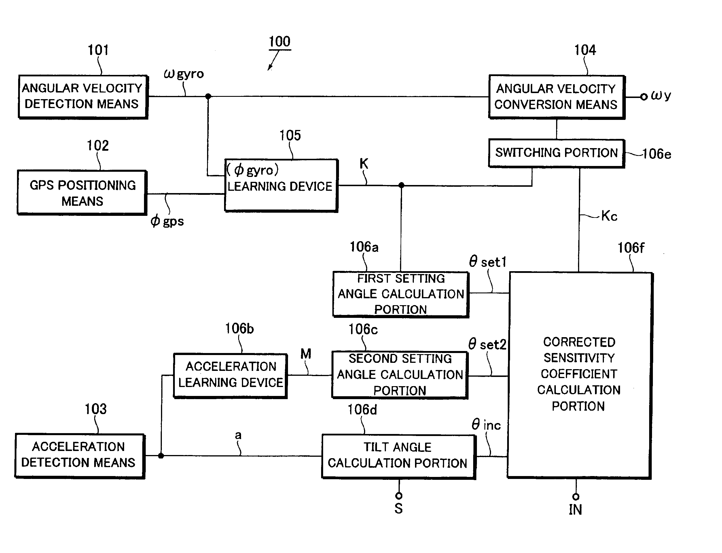
[0091]Now, a more specific example will be described below with reference to FIGS. 6 and 7. FIG. 6 is a block diagram illustrating the configuration of the angular velocity detection device 100 according to this example, FIG. 7 being an explanatory flowchart showing the operation of the angular velocity detection device 100 according to this example.

[0092]In FIG. 6, the like or equivalent components to those of the angular velocity detection device 100 according to the first and second embodiments shown in FIG. 3 are indicated by the like reference symbols.

[0093]Referring to FIG. 6, the angular velocity detection device 100 includes an angular velocity detection portion 101, a GPS positioning portion 102, an acceleration detection portion 103, an angular velocity conversion portion 104, and a calculator 105, which correspond to the angular velocity detection means 101, the GPS positioning means 102, the acceleration detection means 103, the angular velocity conversion means 104, and...


PUM


Abstract

An angular velocity detection device includes an angular velocity detector for delivering a first sensor output corresponding to an angular velocity of a mobile unit; a learning unit for learning a sensitivity coefficient in accordance with the first sensor output and an output provided by a GPS positioning unit; an acceleration detector for delivering a second sensor output corresponding to an acceleration of the mobile unit; a sensitivity coefficient correction unit for determining a corrected sensitivity coefficient in accordance with the sensitivity coefficient and the second sensor output; and an angular velocity converter for multiplying the first sensor output by the corrected sensitivity coefficient to thereby calculate the actual angular velocity of the mobile unit. The angular velocity detection device allows the angular velocity converter to use the corrected sensitivity coefficient to calculate each actual angular velocity of the mobile unit.

Description

BACKGROUND OF THE INVENTION[0001]The present invention relates to an angular velocity detection device for sensing the angular velocity of a mobile unit such as a vehicle.[0002]The present application claims priority from Japanese Patent Application No. 2003-067324, the disclosure of which is incorporated herein by reference in its entirety.[0003]In recent years, vehicle-mounted navigation systems combine the GPS positioning using the GPS (Global Positioning System) and the autonomous navigation using an angular velocity detection device in the form of hybrid positioning so as to compensate for the drawbacks of the GPS positioning and the autonomous navigation. The navigation system then performs map matching for the resulting position information in map data, thereby determining the current location of the vehicle.[0004]Now referring to FIG. 1, the aforementioned angular velocity detection device is designed such that the angular velocity detection device 1 is incorporated into a v...

Claims


Application Information

Patent Timeline
Patent Type & Authority Patents(United States)
IPC IPC(8): B60T8/17B60T8/172G01C21/28G01C21/00G01C19/00
CPCB60T8/172G01C21/28B60T2250/03B60T2210/36
Inventor IMADA, SEIJIENDO, ISAOGOTO, SEIJI
Owner PIONEER CORP
Why Eureka
Try Eureka