Linear object management for a range of flash memory

a technology of flash memory and object management, applied in the direction of memory address/allocation/relocation, instruments, computing, etc., can solve the problems of data cannot be simply overwritten, data is only limited to voice communication, and the amount of memory consumed by data such as voice information and image files can be considerabl

Inactive Publication Date: 2005-05-17
MICRON TECH INC
View PDF21 Cites 57 Cited by
  • Summary
  • Abstract
  • Description
  • Claims
  • Application Information

AI Technical Summary

Problems solved by technology

At one time, cellular phones were only limited to voice communication.
Additionally, the amount of memory consumed by data such as voice information and image files can be considerable, spanning multiple blocks of flash memory.
For example, because of the floating gate structure of conventional flash memory cells, data cannot be simply overwritten.
Additionally, erasing the entire block is a problem, however, in the case where another portion of the memory cells of the block do not need to be updated.
Another issue related to flash, and other floating gate memory devices, is that these memory cells have a limited life-cycle where repeated cycles of erasing and programming degrade memory cell performance.
Eventually, the cell performance is degraded to such a degree that the memory cell can no longer be used to store data.
Conventional memory management software has limitations in the area of data management.
Consequently, if at a later time a different partitioning between code and data is desired, the ranges defined for the two types of data cannot be modified unless software is recompiled.
For example, where information regarding the mapping of data within a memory is maintained in a single table corresponding to one physical block of flash memory, corruption of the single table, such as in the event of a power failure during a write operation to the table, will leave the flash memory device in a questionable state.
Another example is using only a single physical block of flash memory to aid in the reclamation process, which may result in an inefficient iterative write and erase when the data objects stored in memory are large and which may corrupt the data objects if interrupted by a power loss.

Method used


Image

  • Linear object management for a range of flash memory
  • Linear object management for a range of flash memory
  • Linear object management for a range of flash memory

Examples


Embodiment Construction

[0018]Embodiments of the present invention are directed to memory management processes and structures for managing data and code objects in a range of flash memory. In the following detailed description of exemplary embodiments of the invention, reference is made to the accompanying drawings, which form a part hereof, and in which are shown, by way of illustration, specific exemplary embodiments in which the invention may be practiced. These embodiments are described in sufficient detail to enable those skilled in the art to practice the invention. However, it will be clear to one skilled in the art that the invention may be practiced without these particular details. Other embodiments may be utilized and modifications may be made without departing from the spirit or scope of the present invention. The following detailed description is, therefore, not to be taken in a limiting sense, and the scope of the present invention is defined only by the appended claims.

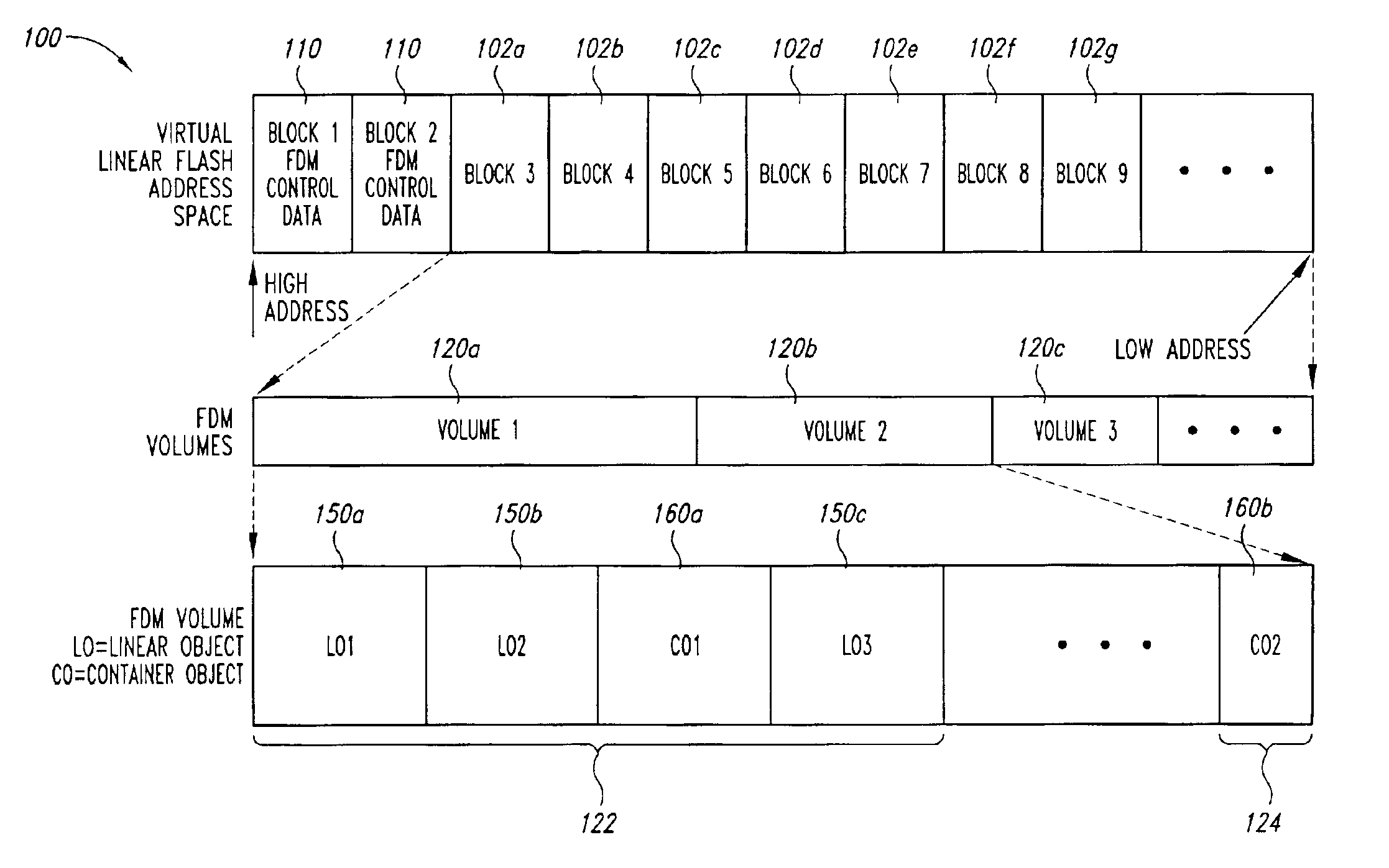
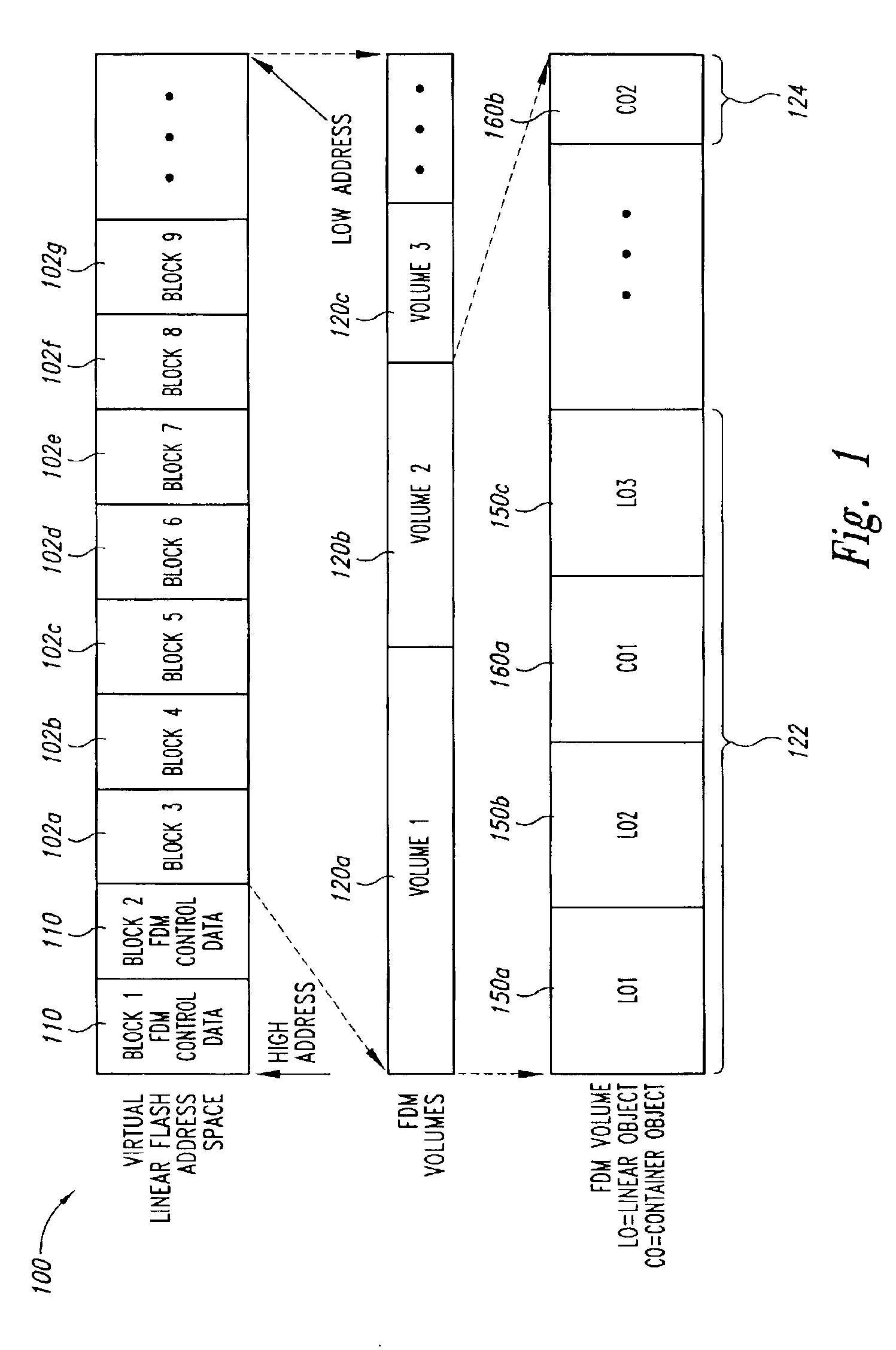
[0019]FIG. 1 shows a d...


PUM


Abstract

Data object management for a range of memory. The range of memory has first and second opposite ends. A plurality of data objects are written to a first contiguous region of memory located at the first end of the range of memory. At least one of the valid data objects of the plurality of data objects are copied to a second contiguous region of memory located at the second end of the range of memory when a reclamation process is requested. The valid data objects copied from the first contiguous region of memory are marked as invalid data in the first contiguous region of memory subsequent to the valid data objects being copied to the second end of the range of memory, and the memory in which invalid data objects in the first contiguous region of memory are located is erased.

Description

TECHNICAL FIELD[0001]The present invention is related generally to the field of data object management, and more particularly, to data object management in semiconductor memory devices, such as flash memory devices.BACKGROUND OF THE INVENTION[0002]Non-volatile memory is a type of memory that can retain data and information even when power is not applied. An example of non-volatile memory that is being used in a variety of applications, such as cellular phone technology, is “flash memory.” Flash memory is a form of electrically erasable programmable read-only memory (EEPROM), where data can be written in bytes and erased in blocks of memory. The blocks of memory typically range from 8 kbytes to 1 MByte in size. The cell density of flash memory devices can be very high, often as high as conventional dynamic random access memory (DRAM) cells, since in conventional flash memory a single floating gate structure is used for each memory cell. Flash memory devices also have relatively fast ...

Claims


Application Information

Patent Timeline
Patent Type & Authority Patents(United States)
IPC IPC(8): G06F12/02
CPCG06F12/0246
Inventor WONG, WANMOLOUIE, ROGERSASINOWSKI, JOHN
Owner MICRON TECH INC
Why Eureka
Try Eureka