Method and arrangement for determining an impact-free extremal actuating position of an actuating member of an internal combustion engine

a technology of actuating position and extremal actuation, which is applied in the direction of mechanical equipment, machines/engines, electric control, etc., to achieve the effect of no additional cost and no additional complexity

Inactive Publication Date: 2005-05-24
ROBERT BOSCH GMBH
View PDF11 Cites 8 Cited by
  • Summary
  • Abstract
  • Description
  • Claims
  • Application Information

AI Technical Summary

Benefits of technology

[0008]A further advantage is that an idle operation is selected as an operating state. In this way, an operating state of the engine is likewise available wherein the engine needs only little air and therefore an actuating member can be shifted in order to measure the characteristic line of the air mass flow and to determine the minimum of this characteristic line. This actuating member is configured as a throttle flap or an exhaust-gas recirculation valve.
[0009]A further advantage is that the measuring operation is interrupted when the idle rpm drops below a pregiven value and that the last-determined measured value is interpreted as an extreme value for the actuating quantity. In this way, an estimate for the extreme value of the actuating quantity results therefore the corresponding set position of the actuating member. This set position is anyway necessary with a suitable selection of the pregiven value in order to maintain the operation of the engine.
[0010]A further advantage is that an exhaust-gas recirculation valve is opened when an intake manifold pressure of the engine drops during the measuring operation below a pregiven critical value especially for a pregiven time.
[0011]A further advantage is that an air quantity or a pressure is used as the actuating quantity, especially the pressure in the intake manifold of the engine. In this way, sensors, which are anyway present in the air supply of the engine, can be used for measuring the actuating quantity so that no additional complexity and no additional costs are necessary.

Problems solved by technology

What is problematic with the through-plunging throttle flap is, however, that the position of the throttle flap 1 with minimum leakage air, that is, the position with minimum air throughout, must be known to the E-Gas system in order to make possible an idle control with very small air mass flows.

Method used


Image

  • Method and arrangement for determining an impact-free extremal actuating position of an actuating member of an internal combustion engine
  • Method and arrangement for determining an impact-free extremal actuating position of an actuating member of an internal combustion engine
  • Method and arrangement for determining an impact-free extremal actuating position of an actuating member of an internal combustion engine

Examples


Embodiment Construction

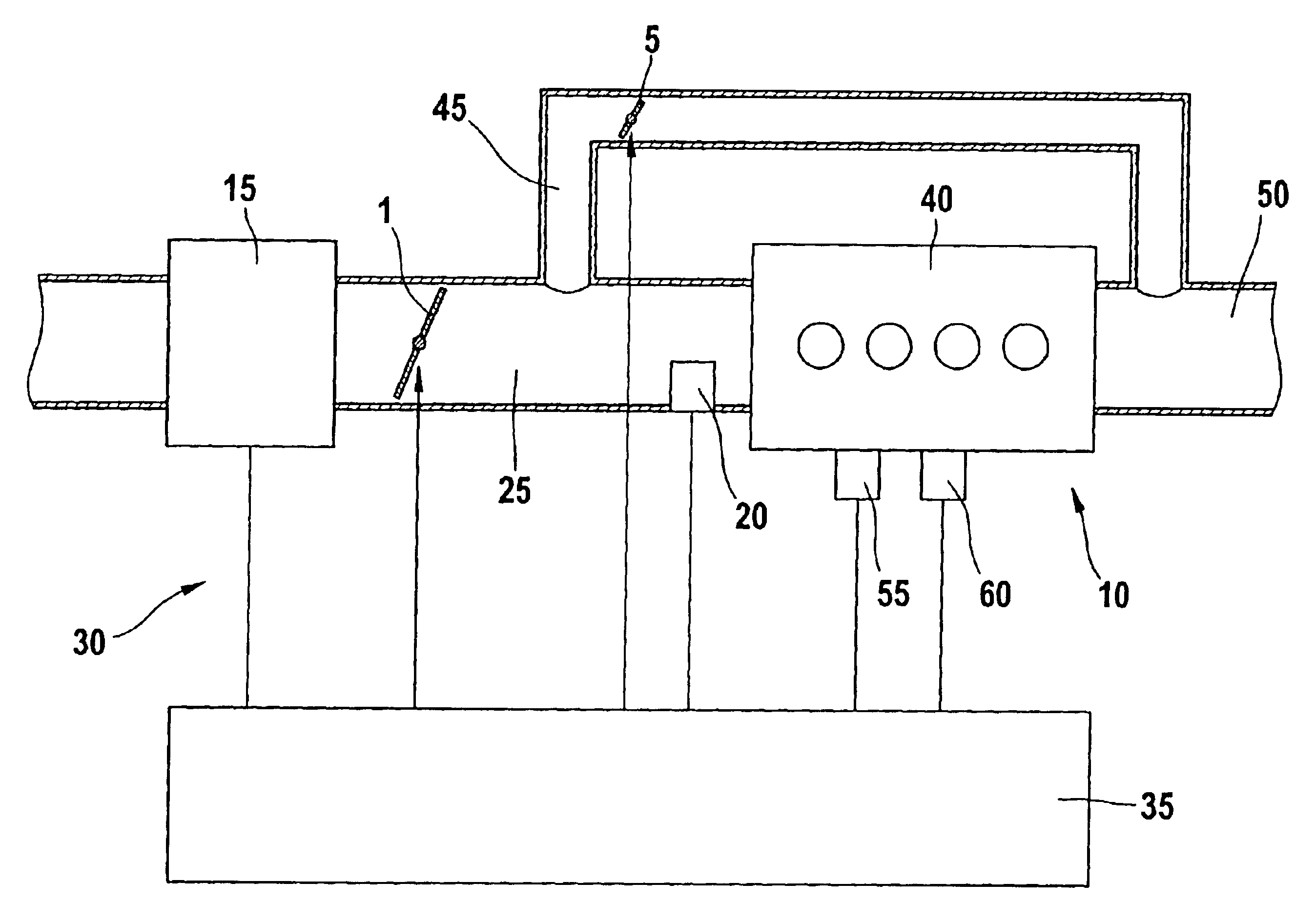
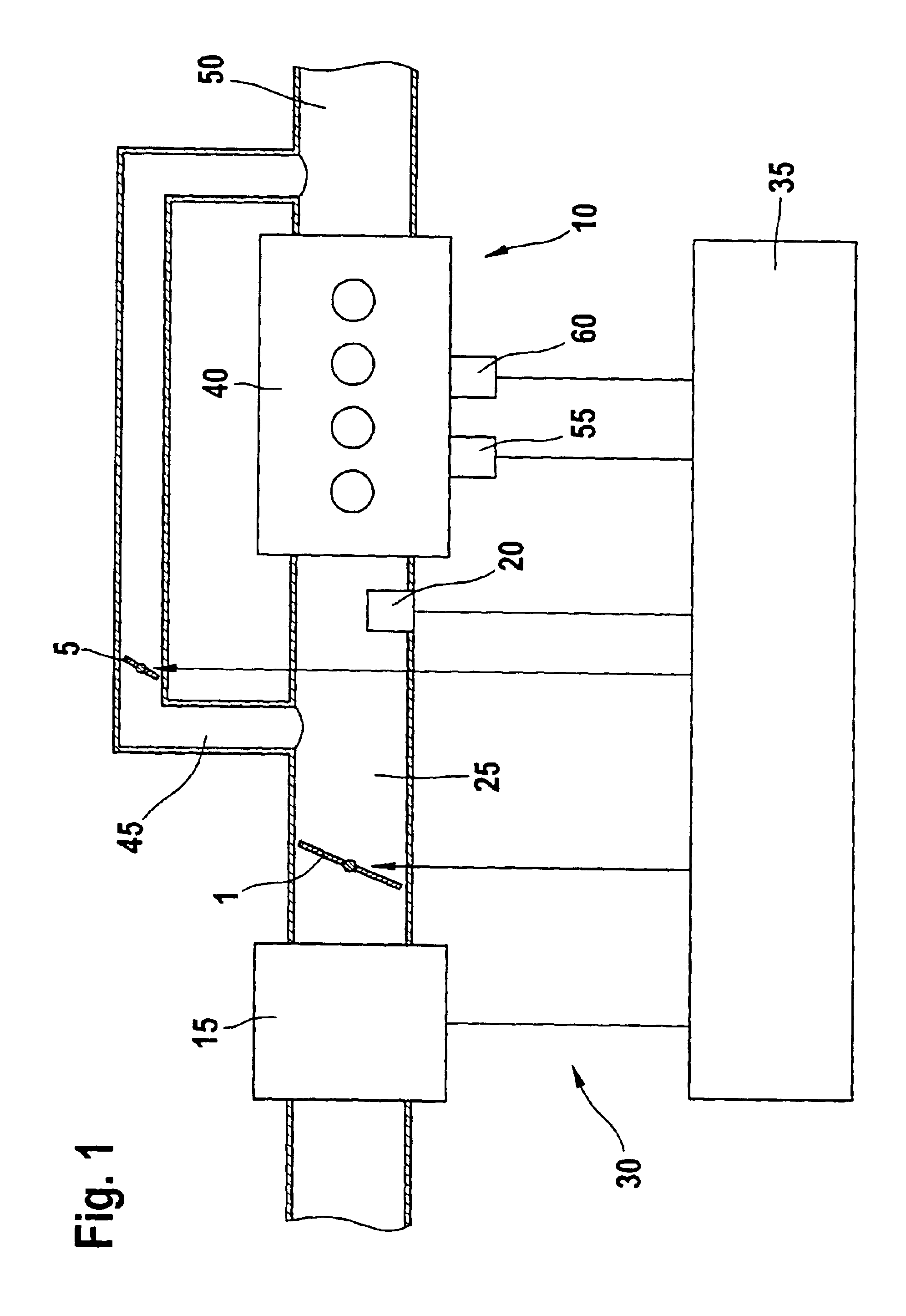
[0022]In FIG. 1, reference numeral 10 identifies an internal combustion engine assembly incorporating an internal combustion engine 40 to which air is supplied via an intake manifold 25. A sensor 15 is mounted in the intake manifold 25 for detecting the air mass flow. The sensor 15 can, for example, be a hot-film air-mass sensor.

[0023]In the following and by way of example, it is assumed that the sensor 15 is such a hot-film air-mass sensor. The air mass flow in the intake manifold 25 is detected by the hot-film air-mass sensor 15 and is supplied to a control 35 which, for example, can be part of the engine control of the internal combustion engine 10. A throttle flap 1 is driven by the control 35 and is mounted downstream of the hot-film air-mass sensor 15 in the intake manifold 25 of, for example, an E-GAS system. An intake manifold pressure sensor 20 is mounted in the intake manifold 25 downstream of the throttle flap 1. An exhaust-gas recirculation channel 45 having an exhaust-g...


PUM


Abstract

A method and an arrangement for determining an impact-free extremal set position of an actuating member (1, 5) of an internal combustion engine (10) provides for an increase of the tolerances in the position of the actuating member and a reduction of the requirements on the mechanics of the actuating member and the read-back accuracy for the set position. In the extremal set position of the actuating member (1, 5), an actuating quantity, which is to be adjusted, has an extreme value. In an operating state of the internal combustion engine (10), which is substantially independent of the set position, the actuating quantity is measured with the aid of a sensor (15, 20) for various set positions in a range wherein the extreme value for the actuating quantity is suspected and that set position is determined as the extremal set position whereat the measured actuating quantity has an extreme value.

Description

BACKGROUND OF THE INVENTION[0001]The use of electrically driven throttle flaps as part of en E-GAS system is already known. Usually, structures are used wherein, at a lower mechanical stop, a position of the throttle flap with minimal air leakage is reached as shown in FIG. 5a. The throttle flap is identified in FIG. 5a by reference numeral 1. FIG. 5d shows a typical position of the throttle flap during driving operation. An upper mechanical stop lies in the vicinity of the maximum possible air throughput. In order to ensure an emergency driving when there is a malfunction of the E-GAS system, there is, as a rule, still a rest position just above the lower mechanical stop and this is the so-called emergency air position of the throttle flap 1 as shown in FIG. 5b. [0002]Systems having a so-called through-plunging throttle flap as shown in FIGS. 4a to 4c are also known. Here, the emergency air position can lie at the lower mechanical stop shown in FIG. 4a or on the side lying opposite...

Claims


Application Information

Patent Timeline
Patent Type & Authority Patents(United States)
IPC IPC(8): F02D9/02F02D11/10F02D21/08F02D45/00
CPCF02D9/02F02D41/0002F02D41/0055F02D41/123F02D41/2425Y02T10/47F02D2009/0284F02D2200/0404F02D2250/16Y02T10/42Y02T10/40
Inventor GROSSMANN, ALEXBAUMANN, TORSTEN
Owner ROBERT BOSCH GMBH
Why Eureka
Try Eureka