Flow diverter for controlling the pressure and flow rate in a CPAP device

a flow diverter and flow rate technology, which is applied in the direction of mechanical equipment, respirators, transportation and packaging, etc., can solve the problems of cpap apparatus response time being delayed, and the upstream valve member of the blower may be choked, etc., to achieve the effect of reducing noise and/or flow fluctuations and increasing response speed

Inactive Publication Date: 2005-05-24
RESMED LTD
View PDF31 Cites 66 Cited by
  • Summary
  • Abstract
  • Description
  • Claims
  • Application Information

AI Technical Summary

Benefits of technology

[0016]It is an aspect of the present invention to provide an improved flow diverter valve and, in a preferred form, a flow diverter valve with reduced noise and / or flow fluctuations and / or increased response speed.

Problems solved by technology

However, this type of valve arrangement may be disadvantageous since during the patient expiration, when the valve member does not permit a significant, if any flow, the blower, which is upstream of the valve member, may be choked.
As such, the response time of the CPAP apparatus when changing from the expiration to the inspiration may be delayed.
This results in the need to supply additional electrical power during times of operational speed increases.
Disadvantages associated with rapid transitions in motor speed are, for example, noise, vibration, blower choking, and increased thermal dissipation requirements, in addition to increased power requirements.
Consequently, venting can be associated with excessive noise when the treatment pressure is adjusted.
Additionally, it is difficult to maintain precise treatment pressure regulation and to maintain a high maximum flow rate, due in part to the large volume of plenum chamber 130.
Imprecise treatment pressure regulation can lead to patient discomfort.
3B), resulting in imprecise, abrupt treatment pressure regulation.
This results in patient discomfort and decreased patient compliance with treatment.
Noise and / or patient discomfort decrease patient compliance with treatment of breathing disorders.

Method used


Image

  • Flow diverter for controlling the pressure and flow rate in a CPAP device
  • Flow diverter for controlling the pressure and flow rate in a CPAP device
  • Flow diverter for controlling the pressure and flow rate in a CPAP device

Examples


Embodiment Construction

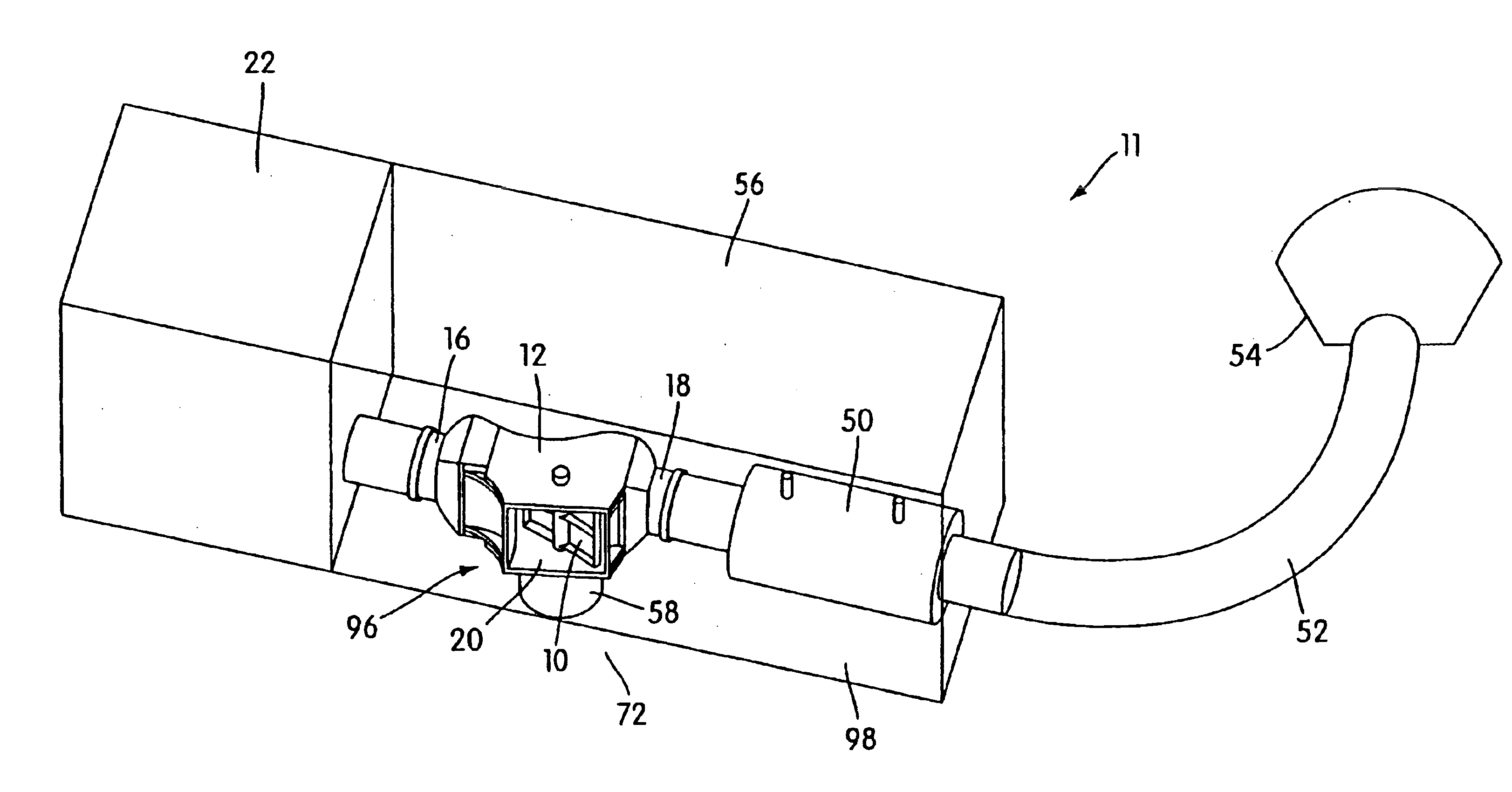
[0045]A ventilatory assistance apparatus 11 according to an embodiment of the present invention is illustrated in FIG. 4. A flow generator 22, in fluid communication with a flow diverter valve 12 via an inlet port 16, provides a flow of air or breathable gas to the flow diverter valve 12 at a generally constant pressure, typically consistent with a maximum treatment pressure. Flow diverter valve 12 includes a vane 10 pivotably mounted within the flow diverter valve 12. Pressure and flow rate of the flow of air or breathable gas from the flow generator 22 are controlled by the flow diverter valve 12 and the vane 10. The flow diverter valve 12 is connected via an outlet port 18 in fluid communication with a flow meter 50, although alternate embodiments could incorporate the flow meter 50 integrally with the flow diverter valve 12. The flow meter 50 is connected in fluid communication with a patient mask 54 via a conduit 52. The flow generator 22, flow diverter valve 12, and flow meter...


PUM


Abstract

A flow diverter valve is used in controlling the pressure and/or flow rate of a breathable gas supplied to the airways of a patient by a breathable gas flow generator supply apparatus during, for example, ventilatory assistance treatments such as non-invasive positive pressure ventilation and nasal Continuous Positive Airway Pressure (CPAP) treatment of Obstructive Sleep Apnea. The flow diverter valve includes a vane and a housing. The housing has an inlet port, an outlet port, and an exhaust port. The exhaust port opens to atmosphere, and the inlet port is in fluid communication with the flow generator. The outlet port is in fluid communication with a patient mask via a conduit. The vane is configured with respect to the housing such that a blower associated with the CPAP apparatus remains substantially unchoked, regardless of whether the vane is in the open or closed position.

Description

[0001]This application is a continuation of U.S. application Ser. No. 10 / 038,583, filed Jan. 8, 2002, now U.S. Pat. No. 6,745,770, incorporated herein by reference in its entirety.BACKGROUND OF THE INVENTION[0002]1. Related Art[0003]This application is related to pending U.S. patent application Ser. No. 09 / 598,053 filed on Jun. 21, 2001, describing a control member for a valve and method for determining fluid flow rate through a valve. This application is also related to U.S. patent application Ser. No. 09 / 642,824 filed on Aug. 22, 2000, describing pressure control in CPAP treatment or assisted respiration. International PCT Patent Application No. PCT / AU97 / 00631 describes varying pressure at a patient mask through the period of treatment during inspiration or expiration, and International PCT patent application No. PCT / AU96 / 00586 describes a flow diverting valve with a rotatable control member, both of which are related to this application. The contents of these U.S. and Internation...

Claims


Application Information

Patent Timeline
Patent Type & Authority Patents(United States)
IPC IPC(8): A61M16/00A61M16/20F16K11/052F16K11/02
CPCA61M16/00A61M16/202F16K11/0525A61M16/20A61M16/0066A61M16/06A61M2016/0039A61M2205/42A61M16/0069A61M16/024A61M16/0866Y10T137/86525
Inventor MCAULIFFE, PATRICK J.BULLOCK, DENIS L.
Owner RESMED LTD
Why Eureka
Try Eureka