
Fan shroud with built in noise reduction

a fan shroud and noise reduction technology, applied in the field of fan shrouds, can solve the problems of high heat produced by the fan while in operation, high noise levels of the powerful fuel cell coolant system fan, and generally impractical vehicle applications, and achieve the effect of reducing the noise associated with the fan

Inactive Publication Date: 2005-05-24
FORD MOTOR CO
View PDF41 Cites 75 Cited by
  • Summary
  • Abstract
  • Description
  • Claims
  • Application Information

AI Technical Summary

Benefits of technology

[0009]Accordingly, an object of the present invention is to provide a system and method to significantly reduce noise associated with air-moving devices such as an electric and / or engine driven axial flow fan or fans (fan).
[0010]Specifically, the present invention is a shroud with a barrel having attached silencers such as Helmholtz resonators to significantly reduce noise associated with airflow and air-moving devices. The invention can be applied to a variety of applications such as a thermal management system for a fuel cell powered vehicle and made from a variety of materials such as plastic or metal. The shroud can, be attached to a heat exchanger or similar structures using various attachment means such as welding, molding, or bolting.

Problems solved by technology

One design challenge for a vehicle with a PEM fuel cell stack is the high amount of heat it produces while in operation.
Unfortunately, noise levels associated with powerful fuel cell coolant system fans are often much higher than acceptable to most operators.
Enclosures using ducts or baffles can also reduce sound / noise but are generally impractical for vehicle applications due to their large size especially if designed to reduce low frequency noise levels.
Thus, the principle limitation with these devices is their ability to attenuate sound energy efficiently only within a limited frequency range.

Method used


Image

  • Fan shroud with built in noise reduction
  • Fan shroud with built in noise reduction
  • Fan shroud with built in noise reduction

Examples


second embodiment

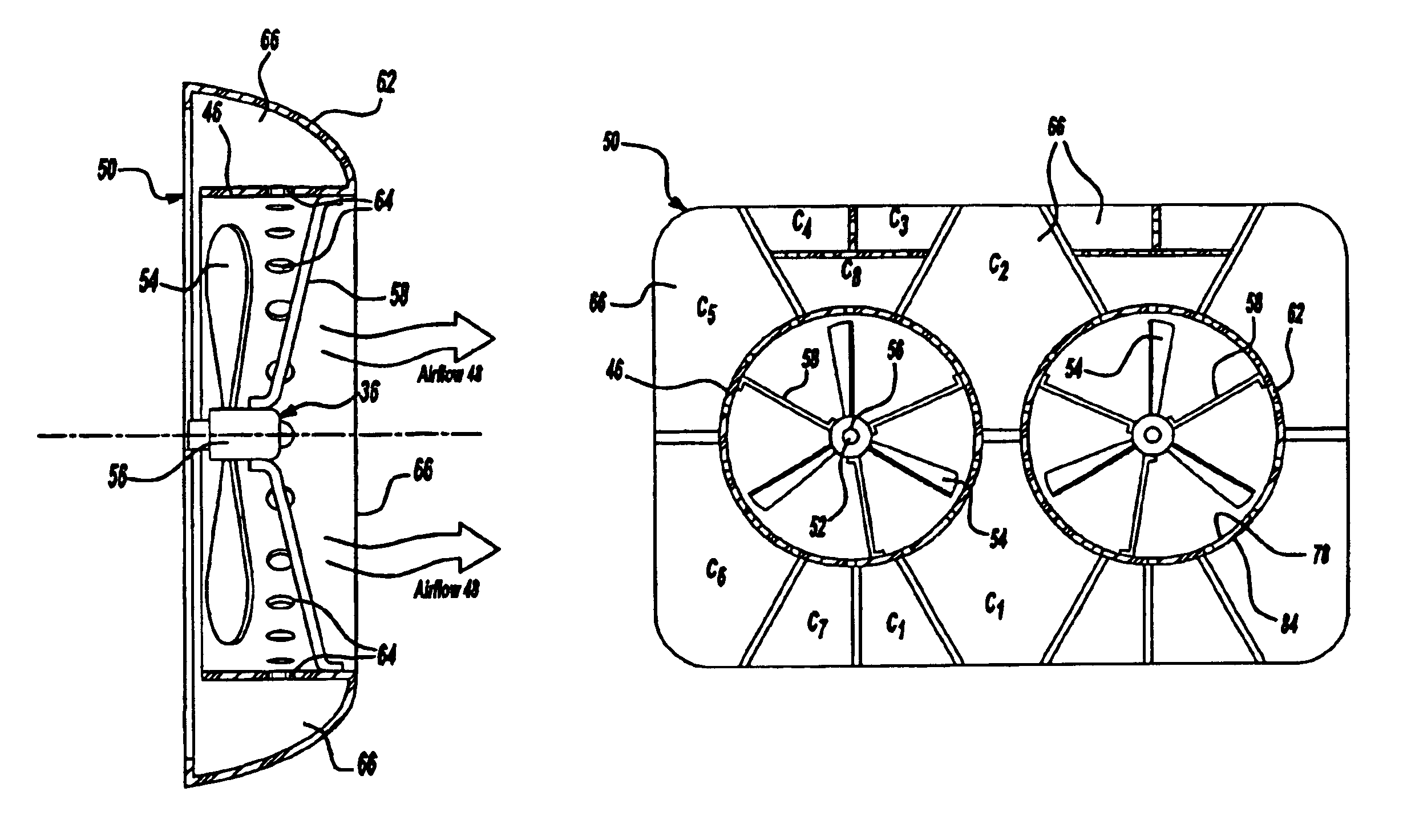
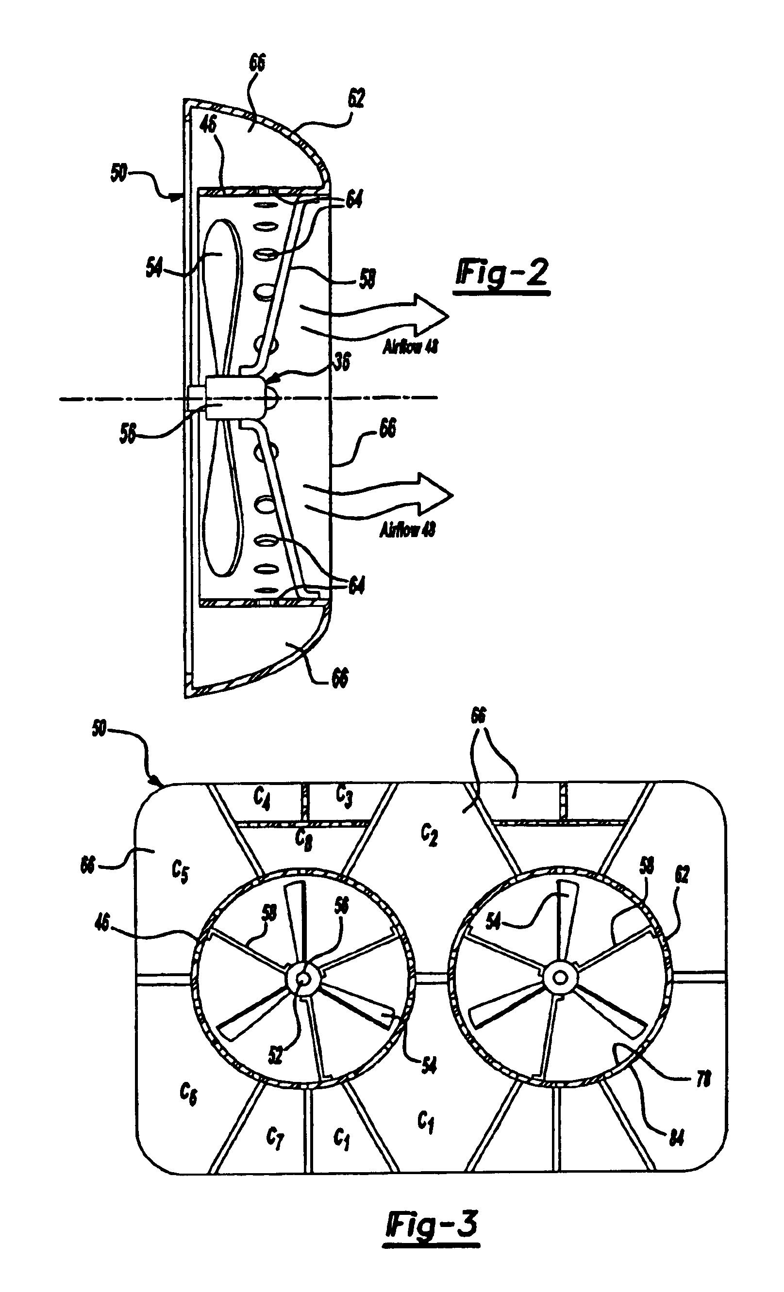
[0040]FIG. 3 illustrates a rear view (viewed toward the direction of the cooling airflow 48) of the present invention having multiple fans 36. This illustration also shows the Helmholtz resonator cavities 66 attached to the fan shroud 50, not the outer barrel 62, and can be arranged in series or in parallel. Cavities C1, C5, C6, and C7 represent cavities 66 arranged in a parallel configuration, while cavities C2, C3, C4, and C8 are arranged in a series configuration. These configurations are still based, as before, on application needs and cavity 66 resonant frequency is a function of the area of the opening 64, on the volume of the cavity air space, and on the length of an air plug formed in the opening 66. The series configuration particularly allows the resonator to be tuned to a lower or broader band.

[0041]FIG. 4 illustrates a side cut away view of a third embodiment of the present invention with the outer barrel 62 extended rearward. This third embodiment also adds stator membe...

fourth embodiment

[0042]FIG. 5 illustrates a side cut away view of the present invention with the outer barrel 62 extended forward.

fifth embodiment

[0043]FIG. 6 illustrates a side cut away view of the present invention with the outer barrel 62 extended both forward and rearward.


PUM


Abstract

The present invention is a system and method to significantly reduce noise associated with air-moving devices such as an axial flow fan using a fan shroud and barrel combination with built in silencers such as Helmholtz resonators. The invention can be applied to a variety of applications such as a thermal management system for a fuel cell powered vehicle. The resonator can be a hollow cavity in networks attached to an outer or inner barrel or shroud and tuned to reduce noise at predetermined noise frequency ranges within the airflow. The invention can also attach stator members on the inner surface of the outer barrel to further reduce noise. Additional sound absorbing material, such as steel wool, can be disposed within the resonator cavity.

Description

BACKGROUND OF INVENTION[0001]The present invention relates generally to silencers for air-moving devices and specifically to a method and apparatus to reduce fan noise of a thermal management system using resonators integrated with fan shrouds and barrels.[0002]In an effort to find new energy sources, fuel cells using an electrochemical reaction to generate electricity are becoming an attractive energy alternative. Fuel cells offer low emissions, high fuel energy conversion efficiencies, and low noise and vibrations. U.S. Pat. No. 5,248,566 to Kumar et al. These advantages make fuel cells useful in automotive applications. Of the various types of fuel cell types, the proton electrolyte membrane (PEM) fuel cell appears to be the most suitable for use in automobiles, as it can produce potentially high energy, but has low weight and volume.[0003]One design challenge for a vehicle with a PEM fuel cell stack is the high amount of heat it produces while in operation. Thermal management sy...

Claims


Application Information

Patent Timeline
IPC IPC(8): F01P5/06F01P5/02F15D1/02F15D1/00F04D29/58F04D29/66
CPCF01P5/06F15D1/02F04D29/665F04D29/582
Inventor SHAH, HEMANT S.HOLLINGSHEAD, JOHN STUARTWANG, JOHNTHAWANI, PRAKASH TULJARAMKOSIK, RICHARD CHARLESKUMAR, MUKESH
Owner FORD MOTOR CO
Learn More