Vehicle storage box structure

a storage box and vehicle technology, applied in the direction of roofs, pedestrian/occupant safety arrangements, vehicular safety arrangements, etc., can solve the problems of increased discomfort of passengers, and increased rigidity of the main body of the slide rail. , to achieve the effect of reducing the overall strength reducing the rigidity of the main body of the slide rail, and softening the reaction for

Inactive Publication Date: 2005-05-24
NISSAN MOTOR CO LTD
View PDF15 Cites 23 Cited by
  • Summary
  • Abstract
  • Description
  • Claims
  • Application Information

AI Technical Summary

Benefits of technology

[0007]One method of resolving this problem is to make the slide rails with a thin-walled structure to reduce the overall strength of the slide rails and soften the reaction force that occurs when a knee contacts a slide rail. However, secondary problems are unavoidable with such a solution. For example, one can easily imagine a situation in which a heavy object is stored in the glove box and the slide rails are damaged because they cannot tolerate the downward load. Also, since the rigidity of the main body of the slide rails is reduced, the glove box will feel flimsy when it is opened and closed. Moreover, since the rigidity of the main body of the slide rails is reduced, the glove box will readily shake due to the vibrations of the vehicle when it is open. In short, the quality of the glove box in relation to opening and closing will decline, if the slide rails are constructed with a thin wall walled structure.
[0008]The object of the present invention is to solve the problems just described by providing a vehicle storage box mounting structure that reduces the discomfort felt by the passenger when the passenger's knees penetrate or hit the storage box during a front collision without significantly reducing the strength and rigidity of the slide rails overall.

Problems solved by technology

It has been discovered that during a front collision, the passenger's knees will sometimes penetrate the instrument panel.
When this occurs, there is the possibility that the passenger will experience increased discomfort if the passenger's knees hits the slide rails, which are made of iron or other high-hardness material.
However, secondary problems are unavoidable with such a solution.
For example, one can easily imagine a situation in which a heavy object is stored in the glove box and the slide rails are damaged because they cannot tolerate the downward load.
Also, since the rigidity of the main body of the slide rails is reduced, the glove box will feel flimsy when it is opened and closed.
Moreover, since the rigidity of the main body of the slide rails is reduced, the glove box will readily shake due to the vibrations of the vehicle when it is open.
In short, the quality of the glove box in relation to opening and closing will decline, if the slide rails are constructed with a thin wall walled structure.

Method used


Image

  • Vehicle storage box structure
  • Vehicle storage box structure
  • Vehicle storage box structure

Examples


second embodiment

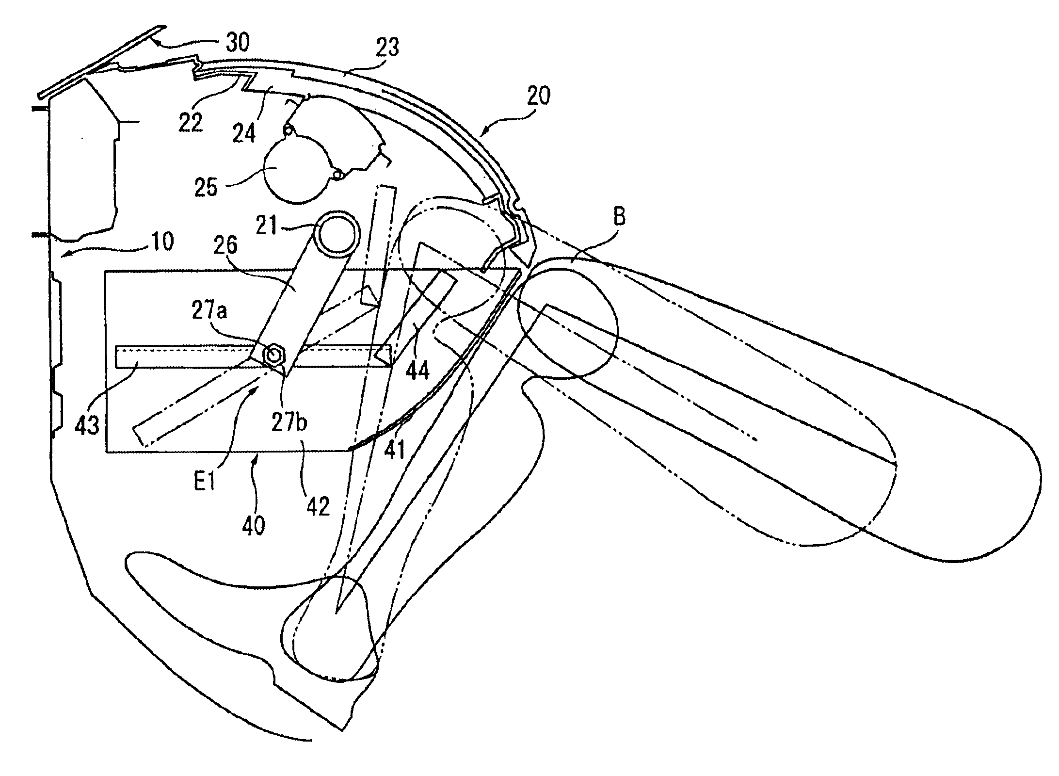
[0026]Referring now to FIGS. 4 and 5, a vehicle storage box mounting structure is illustrated with another vehicle mounting arrangement having an energy absorbing arrangement E3 in accordance with a second embodiment. In view of the similarity between the first and second embodiments, the descriptions of the parts of the second embodiment that are identical to the parts of the first embodiment may be omitted for the sake of brevity. Moreover, the parts of the second embodiment that are the same as the first embodiment will be given the same reference numeral, while the parts that differ from the parts of the first embodiment will be indicated with a single prime (′).

[0027]In this second embodiment, the slide rails 43 of the first embodiment have been replaced with a pair of slide rails 43′ (slide mechanism) and the brackets 26 have been replaced with a pair of shorter brackets 26′. The slide rails 43′ of the slide mechanism are mirror images of each other. Thus, only one the slide r...

third embodiment

[0031]Referring now to FIG. 6, a vehicle storage box mounting structure is illustrated with another vehicle mounting arrangement having an energy absorbing arrangement E4 in accordance with a third embodiment. In view of the similarity between the first and third embodiments, the descriptions of the parts of the third embodiment that are identical to the parts of the first embodiment may be omitted for the sake of brevity. Moreover, the parts of the third embodiment that are the same as the first embodiment will be given the same reference numeral.

[0032]In this second embodiment, the brackets 26 of the first embodiment have been replaced with a pair of shorter brackets 28. The brackets 28 are identical to each other. Thus, only one the brackets 28 is illustrated. This embodiment is the same as the previous embodiments in that the slide rails 43 are mounted to the vehicle (to the steering member 21 in this embodiment) through brackets 28 in such a manner that the slide rails 43, but ...


PUM


Abstract

A vehicle storage box mounting structure is configured to reduce the discomfort felt by the passenger when the passenger's knees hit the storage box during a front collision without significantly reducing the strength and rigidity of the slide rails overall. The vehicle storage box mounting structure serves to mount a storage box to a vehicle in such a manner that the storage box can be moved between two positions, a stored position and a pulled out position, by slide rails provided on both sides of the storage box. The vehicle storage box mounting structure is configured such that at least a portion of the slide rails can be made to swing in response to an input force to the storage box from a passenger during a front collision.

Description

BACKGROUND OF THE INVENTION[0001]1. Field of the Invention[0002]The present invention generally relates to a mounting structure for a vehicle-use storage box, e.g., a sliding glove box. More specifically, the present invention relates to a vehicle-use storage box structure having slide rails that are arranged in an area where the passenger's knee(s) may likely contact one of slide rails during a front collision.[0003]2. Background Information[0004]Known vehicle storage box mounting structures include the mounting structure of the sliding glove box. The sliding glove box has slide rails arranged on the left and right sides of the glove box main body. A vehicle body panel exists to the front of the slide rails and the lid of the glove box or the instrument panel exists to the rear of the slide rails. In order to achieve the longest possible slide distance, the full length of the slide rails is set be as long as possible within the space between the vehicle body panel and the glove box...

Claims


Application Information

Patent Timeline
Patent Type & Authority Patents(United States)
IPC IPC(8): B60R21/04B60R21/045B60R21/00B60R21/02B60R7/06
CPCB60R21/045B60R2021/0051B60R7/06
Inventor OKANDA, TORUISHII, TOORU
Owner NISSAN MOTOR CO LTD
Why Eureka
Try Eureka