
Intradiscal lesioning device

a technology of disc lesioning and stent, which is applied in the field of radio frequency electrical energy, can solve the problems of large proportion of health care funds, disc abnormalities and pain, and debilitating conditions of patients

Inactive Publication Date: 2005-05-24
AVANOS MEDICAL SALES LLC
View PDF41 Cites 223 Cited by
  • Summary
  • Abstract
  • Description
  • Claims
  • Application Information

AI Technical Summary

Benefits of technology

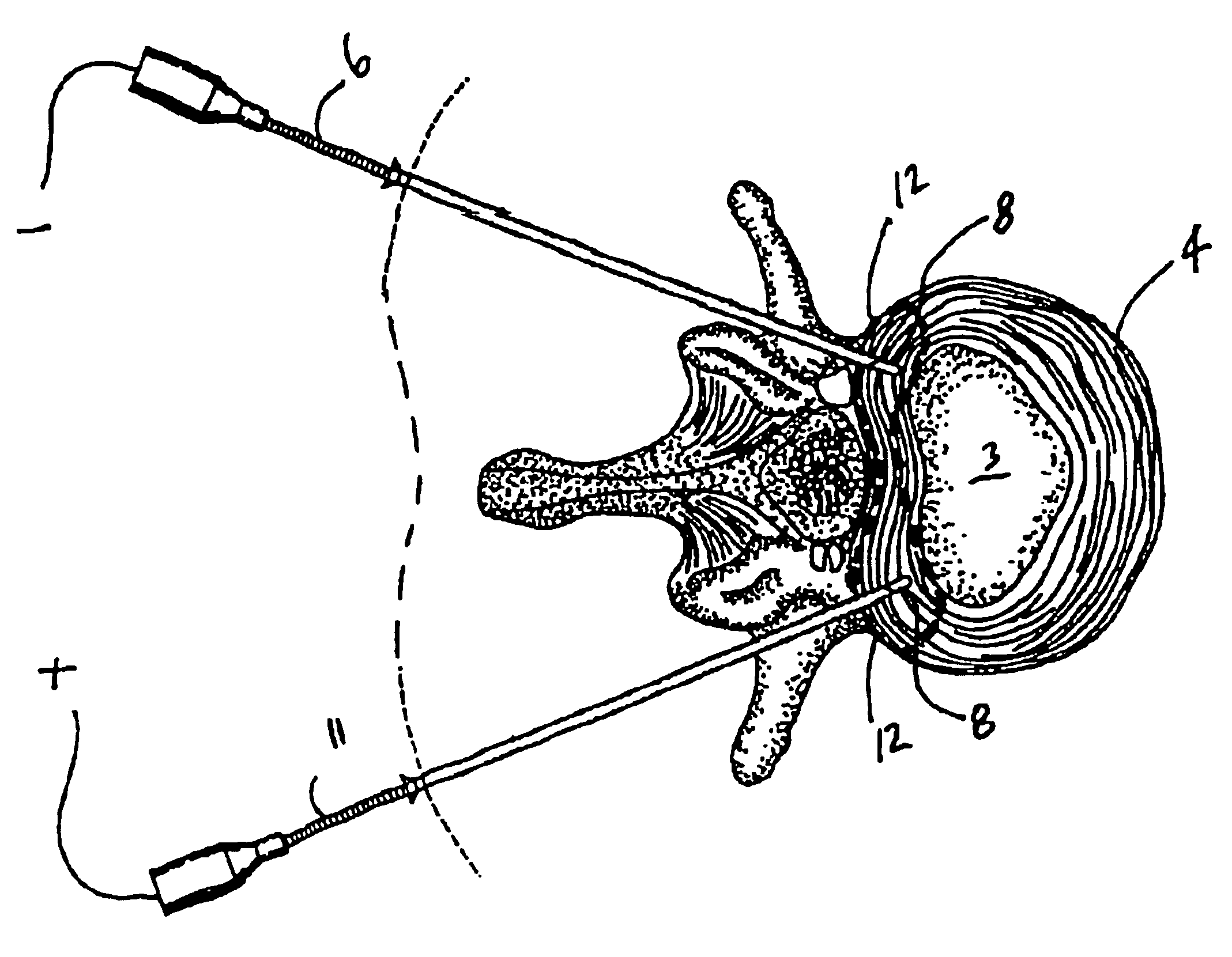
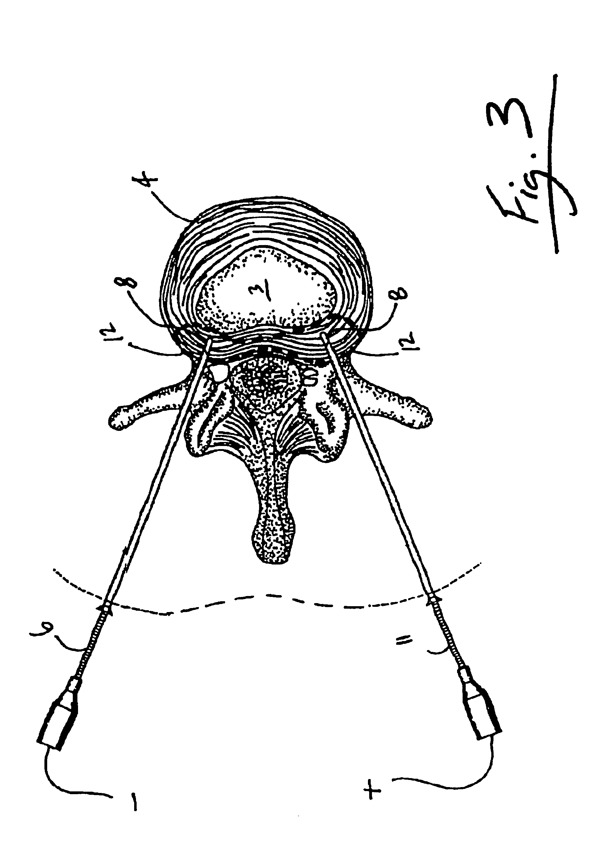
[0029]The device can also have two elongate introducer tubes each having an inner end, an outer end and a longitudinal hollow bore extending therebetween, for percutaneous surgical insertion to two spaced apart treatment sites of the annulus fibrosus thereby providing external surgical access to the annulus fibrosus through each bore. The elongate probes are longitudinally inserted through the bore from the inner to the outer end of the introducer tube. The distal portions of each probe energy delivery means for delivering energy between opposing distal portions of the probes through the annulus fibrosus adjacent the two treatment sites, for denervating and stiffening the annulus fibrosus. Preferably the energy is electrical current having a frequency within the radio frequency range or at least above physiological stimulation range. Since the annulus fibrosus has an impedance less than the tissue surrounding the disc, the device can also include an electrical current impedance meter communicating between the distal portions of each probe to determine the position of the electrodes, determine whether cracks or fissures are present in the annulus fibrosus which increase impedance and to determine the optimal level of power needed to effectively treat the section of the annulus fibrosus.

Problems solved by technology

Lower back injuries and chronic back pain are a major health problem resulting not only in a debilitating condition for the patient, but also in consuming a large proportion of funds allocated for health care, social assistance and disability programs.
Disc abnormalities and pain may result from trauma, repetitive use in the workplace, metabolic disorders, inherited proclivity or aging.
The existence of adjacent nerve structures and innervation of the disc are very important issues in respect to patient treatment for back pain.
For most patients, however, a well-defined abnormality cannot be found to solely explain the cause of the low back pain, making treatment and pain management very difficult.
The annulus fibrosus is thinner nearer to the posterior than to the anterior margin of the disc, and many disc ruptures occur in the posterior region thereby exerting pressure on the adjacent nerve fibers causing pain.
Another cause of pain resulting from disc pathology is chemically induced pain.
This is also a cause of sciatica.
Such major surgical procedures are highly invasive, expensive and involve significant risk.
Furthermore motion is impeded once the vertebrae are fused and there may be adverse mechanical effects on the adjacent remaining discs.
However, these methods cause damage to the nucleus pulposus, which is essential to the maintenance of the disc.
Further, the damaged annulus fibrosus is not treated.
These known methods do not allow applying energy to these target areas without unnecessarily entering and applying energy to the nucleus pulposus.
There are several disadvantages to unnecessarily entering into and applying energy to the nucleus pulposus.
Disadvantages include disrupting the metabolism of the intervertebral disc, impeding the healing processes, and altering the structure of healthy tissues of the disc such as the cartilage endplates, nucleus pulposus and areas of the annulus fibrosus that are not targeted.
Additional disadvantages include causing unnecessary physical damage, increasing the risk of discitis, and potentially removing nuclear material that can come in contact with other adjacent tissues thus causing biochemical damage.
The manipulation of prior art probes within the nucleus pulposus to position an energy emitter close to the site of the annulus injury appears to be largely unnecessary since heat is readily conducted throughout the nucleus pulposus no matter where the probe is located within the nucleus.
Clearly the prior art is less than optimal since these techniques involve damage to the annulus fibrosus which is pierced to gain access to the nucleus pulposus.
However, tunneling through the layers of the annulus fibrosus can significantly damage the annulus fibrosus and layers may peel apart.
Surgical manipulation involves inaccuracies and in the case of ruptured or fissured discs, tunneling may cause further deterioration of the annulus fibrosus.

Method used


Image

  • Intradiscal lesioning device
  • Intradiscal lesioning device
  • Intradiscal lesioning device

Examples


Embodiment Construction

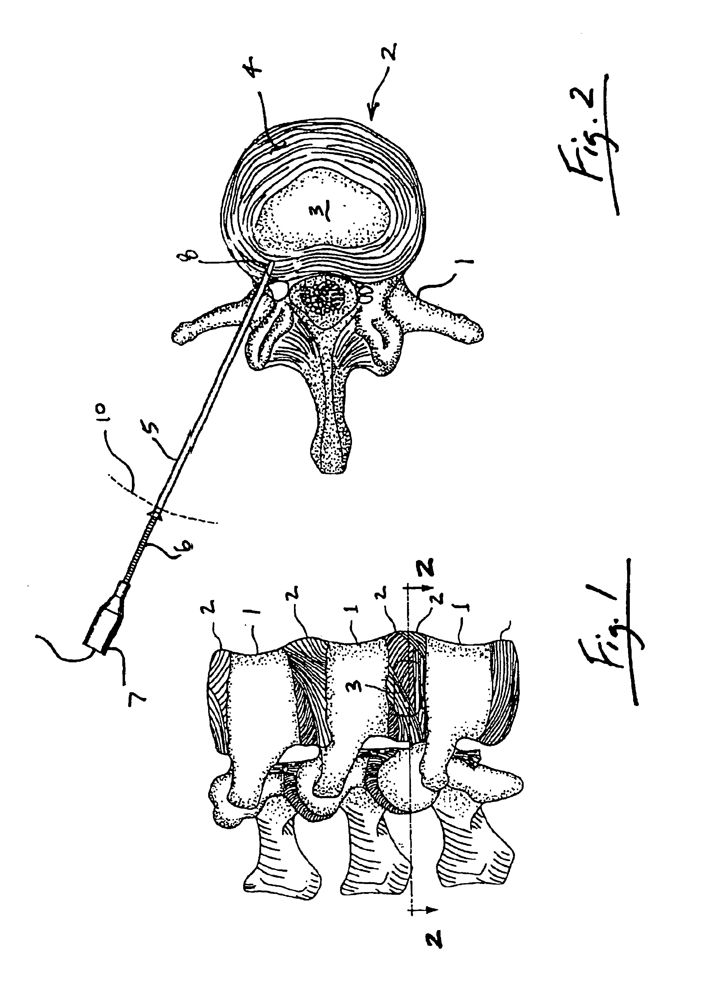
[0047]FIGS. 1 and 2 illustrate a section of a patient's vertebrae 1 and a typical uninjured intervertebral disc 2. The centrally located nucleus pulposus 3 is bounded by the annulus fibrosus 4 and the cartilage endplates (not shown). The cartilage endplates are joined to the vertebrae above and below the intervertebral discs. Metabolites diffuse from blood vessels in the vertebrae 1 through the cartilage endplates to the nucleus pulposus 3 and annulus fibrosus 4. FIG. 2 shows one embodiment of a first probe 6 is inserted through an introducer tube 5, also referred to as a catheter tube. The proximal portion 7 of probe 6 is connected to an electrical power source (not shown). In the embodiment shown in FIG. 2, the distal portion 8 of the probe 6 is inserted partially into the annulus fibrosus 4 to conduct electrical current or apply heat thereto as further described with reference to FIG. 3.

[0048]Although some of the figures and the description relate to the percutaneous insertion of...


PUM


Abstract

An intradiscal device for treatment of a patient's intervertebral disc. The device has two elongate probes for insertion to two spaced apart treatment sites of the annulus fibrosus. The distal portions of each probe have energy delivery means for delivering energy between the distal portions of the probes through the annulus fibrosus adjacent the two treatment sites. The energy is preferably electrical energy the probes may be inserted surgically through respective elongate introducer tubes.

Description

TECHNICAL FIELD[0001]The invention relates to a method and apparatus for applying energy, particularly radio frequency electrical energy, to a region of the annulus fibrosis of an intervertebral disc in treatment of intervertebral disc disorders using two percutaneous probes.BACKGROUND OF THE ART[0002]The human intervertebral junction is characterized principally by an intervertebral disc interposed between adjacent vertebral surfaces. The size and configuration of discs vary between the six discs of the cervical region, the twelve discs of the thoracic region, six of the lumbar region and one disc between the sacrum and coccyx.[0003]Intervertebral discs are neither homogeneous nor static. Changes to a disc can affect the vertebral column activity significantly. The intervertebral disc is a complex structure where its dynamic properties result from the interaction of a central, gelatinous nucleus pulposus encircled by a tough, fibrous, semielastic annulus fibrosus. Further, thin car...

Claims


Application Information

Patent Timeline
IPC IPC(8): A61B18/14A61B18/00
CPCA61B18/148A61B18/18A61B2018/00023A61B2018/00875A61B2018/0044
Inventor LEUNG, MARK SSHAH, KRISHANBAYLIS, FRANK H
Owner AVANOS MEDICAL SALES LLC
Learn More