
Fractional deionization process

a deionization process and ionization technology, applied in the direction of ion exchange, liquid/fluent solid measurement, peptides, etc., can solve the problems of scaling of more strongly ionized species, and achieve the effects of facilitating the removal of more weakly ionized species, efficient removal, and energy saving

Inactive Publication Date: 2005-05-24
AQUATECH INT LLC
View PDF27 Cites 34 Cited by
  • Summary
  • Abstract
  • Description
  • Claims
  • Application Information

AI Technical Summary

Benefits of technology

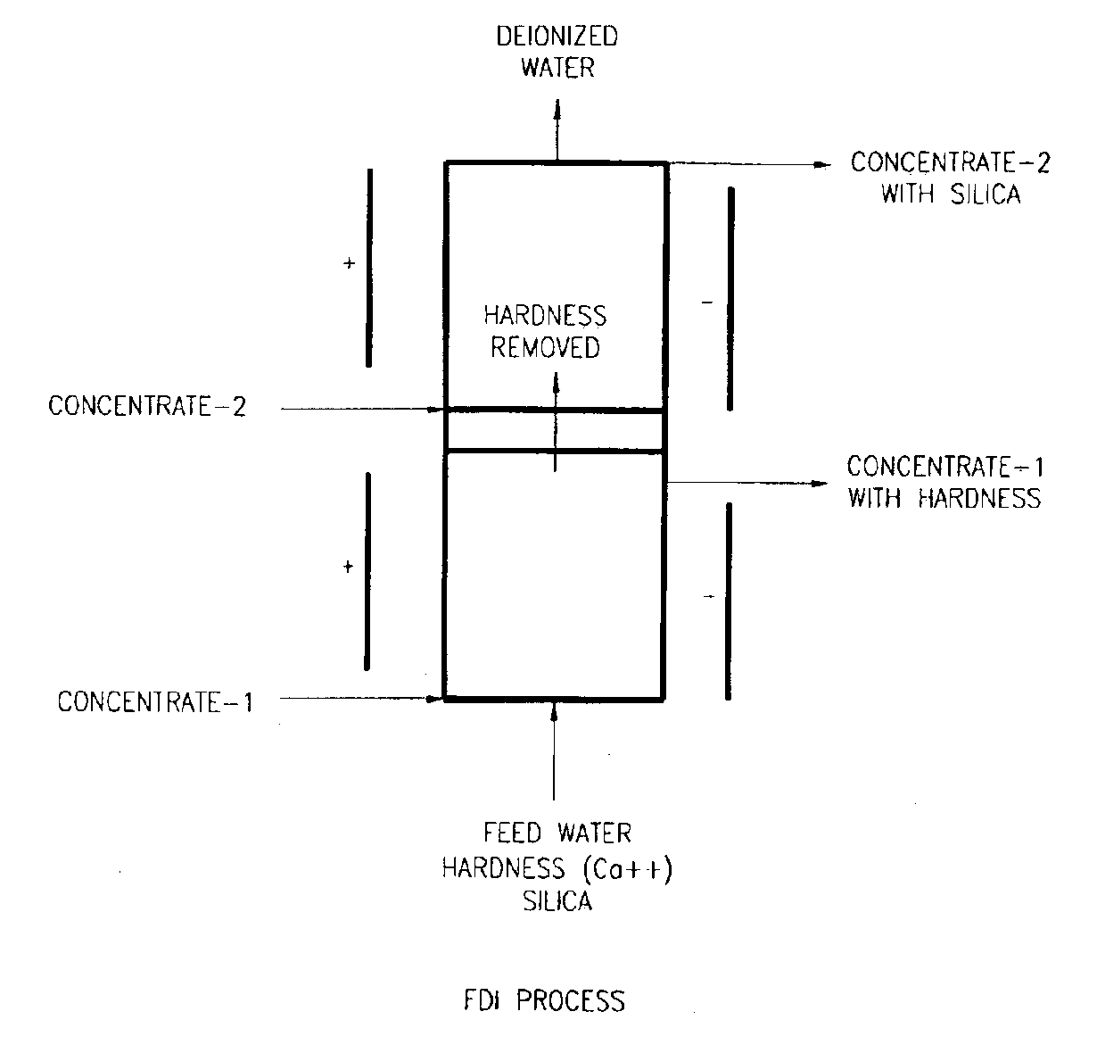
[0017]After the feed stream has passed through the first deionization module it becomes the first product stream. Although strongly ionized contaminant species have been substantially eliminated from the first product stream through operation of the first deionization module, a number of more weakly ionized species may remain. The first product stream is therefore introduced into a second deionization module. A second voltage is applied to the second deionization module. Greater than the first voltage, the second voltage is calculated to facilitate removal of more weakly ionized species than were removed in the first module. In conventional electro-deionization, application of a voltage of sufficient strength to remove more weakly ionized species tends to cause scaling of the more strongly ionized species due to creation of an unfavorable pH. In the instant invention such strongly ionized species are no longer present after having been removed in the first deionization module. Weakly ionized species may therefore be efficiently removed without fear of scaling. The process therefore becomes more energy efficient.

Problems solved by technology

In conventional electro-deionization, application of a voltage of sufficient strength to remove more weakly ionized species tends to cause scaling of the more strongly ionized species due to creation of an unfavorable pH.

Method used


Image

  • Fractional deionization process
  • Fractional deionization process
  • Fractional deionization process

Examples


case-1

[0069]The feed water has an impurity of calcium ions. The feed pH is between 6 and 6.5 with an occasional rise up to 7.5.

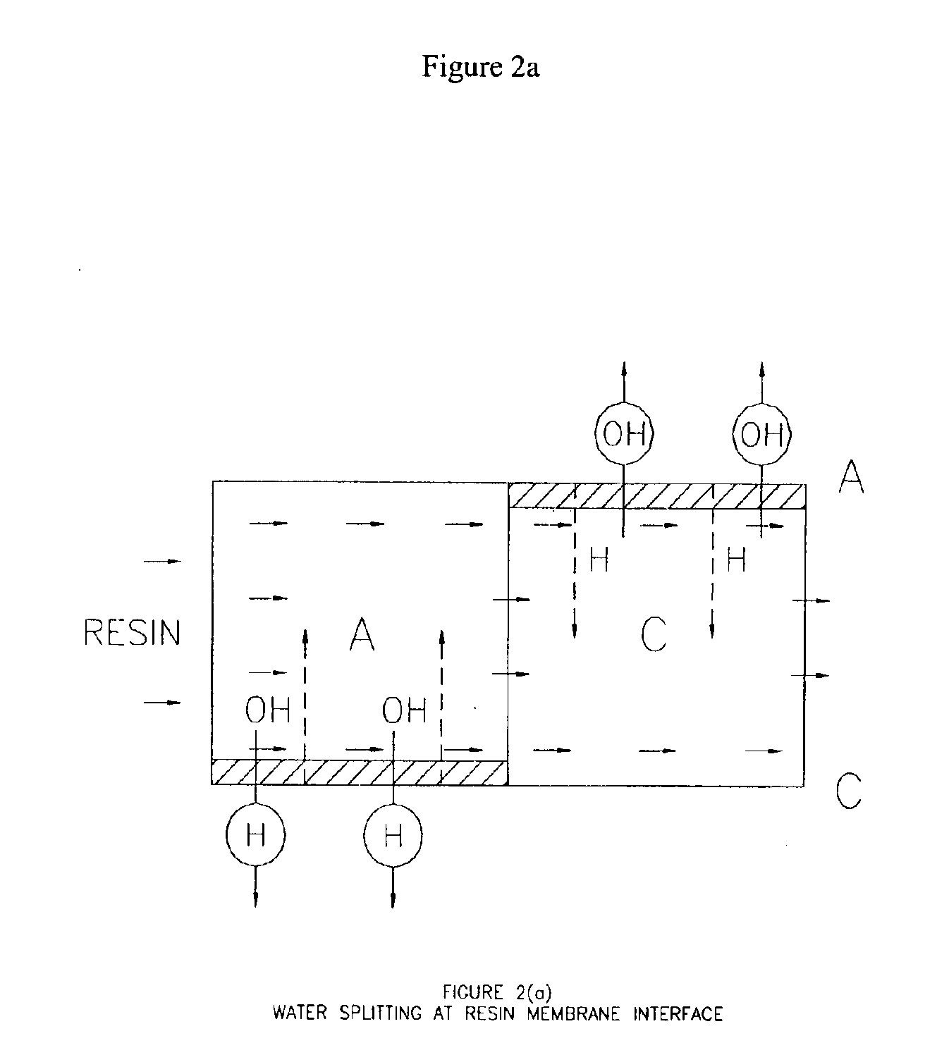
[0070]All the calcium ions are separated in the reject side such that the product received contains no calcium and the reject side is loaded with the calcium ions. There are fewer calcium ions in the feed side than in the reject side. Precipitation in the reject side should be avoided, and to achieve this condition, the reject side pH should be slightly acidic; more H+ ions should be transferred along with the cations. Maintaining pH below neutral would be enough to prevent calcium precipitation; any more would be a waste of energy.

[0071]On the other side, in the feed chamber, basicity needs to be avoided. If the pH of the product is neutral or near neutral, the process would run more smoothly. Because more H+ ions are used in the reject side, that many more OH− ions would find their way into the product after getting consumed, so if the product pH is not neutral,...

example 01

[0077]Two normal stacks, each of two cell pairs, made the initial dual voltage system with dilute chambers separately and connecting them in series such that feed and concentrate were fed in the first stack, and the product and the reject of first stack were the feed for the second stack.

[0078]The effective membrane characteristics in the stacks used for all the trial runs were:[0079]Dimensions: 190 mm wide and 350 mm long.[0080]Dilute chambers: two numbers in each stage.[0081]Operating membrane surface area 1330 cm2 in each stage.[0082]Total surface area 2660 cm2 in both the stages.[0083]Bed length 0.7 m per stage and 1.4 m in total.

[0084]Product flow rate achieved in this design was 0.56 to 0.71 cm3 per minute per cm2 of surface area. The results of this trial are set forth in Table 3.

[0085]

TABLE 3HardnessFeedFeedProductConcConc outCalcium as CaCO3PrFlowCondCondVoltsAmpsFlowCondFeedProductpsicc / minus / cmpHus / cmpHV / pairadccc / minus / cmpHppmppm36180022.36.54.68.564.750.197202803.963618...

case-2

[0087]The feed water has impurities of silica and carbonic acid. The feed pH is between 6 and 6.5.

[0088]All the anionic impurities are separated from the feed to give a product free of silica and carbonic acid, and the reject collects all the separated ions. For this to happen, enough OH− ions have to be produced in the feed chamber for the reaction to occur. High energy is also required so that the concentration is maintained at a high enough level on the membrane surface for easy transfer. This would allow more OH− ions to transfer across as well. As a result the pH of the reject side would be basic, while the product side would remain neutral.[0089]Reject: pH neutral→towards basic.[0090]Product: pH slightly acidic→towards neutral.

Stage-2 Effect

The feed in this stage contains as impurities primarily the weakly ionized species that were not eliminated in the first stage. As was previously explained, both silica and carbonic acid groups require OH− ions and high energy for ionizatio...


PUM

PropertyMeasurementUnit
Electrical resistanceaaaaaaaaaa
Fractionaaaaaaaaaa
Fractionaaaaaaaaaa

Abstract

A liquid treatment process is described for sequential removal of ionic species of progressively decreasing ionic strength without precipitation or “scaling.” An aspect of the invention includes dual electrodeionization operations. The first electrodeionization operation is performed at a voltage calculated to remove strongly ionized species such as calcium and magnesium from the feed water without scaling. The product of the first electrodeionization operation is then subjected to a second electrodeionization operation. The second electrodeionization operation is performed at a voltage greater than the first electrodeionization operation, and is designed to remove more weakly ionized species such as silica and carbon dioxide, preventing scaling. More than two successive electrodeionization operations may be performed if desired. Multiple electrodeionization operations may occur in a single electrodeionization stack or in multiple electrodeionization stacks.

Description

CROSS-REFERENCE TO RELATED APPLICATIONS[0001]This application claims the benefit of co-pending provisional patent application Ser. No. 60 / 343,323 entitled “Fractional Deionization Process”, filed on Dec. 20, 2001, the entire disclosure of which is incorporated by reference herein.FIELD OF THE INVENTION[0002]The present invention relates to a novel technique for removal of ionic species from a feed stream without creating any scaling, even at higher levels of inlet water hardness. The invention deionizes water using a controlled process system that allows the removal of some ionic components separately from other ionic components without causing any scaling problem in the dilute or concentrate compartment of the cell. Such scaling has been the limiting operating condition of preexisting electrodeionization (“EDI”) systems and explains the lack of commercial success for such systems. Generation of H+ and OH− ions at controlled conditions with proper pH controls in the fractional deion...

Claims


Application Information

Patent Timeline
IPC IPC(8): B01J47/08B01J47/00B01D61/42B01D61/48B01D61/52C02F1/469C02F1/46C02F1/42C02F5/00B01D61/50B01D61/44C02F1/00C02F1/68C02F11/00C02F11/18
CPCB01D61/48B01J47/08C02F1/003C02F1/005C02F1/4602C02F1/4695C02F1/68C02F11/18B01D61/52C02F2201/46125C02F1/42C02F1/4604C02F1/4693C02F5/00C02F11/00C02F2201/46115C02F1/469
Inventor CHIDAMBARAN, RAVISHARMA, DEVESHRAINA, PAVAN
Owner AQUATECH INT LLC
Learn More