Motor

a motor and rotor technology, applied in the field of motors, can solve the problems of reducing the area of the weight, reducing and increasing the vibration generated by the pager motor, so as to reduce the size of the motor and increase the torque

Inactive Publication Date: 2005-05-24
CANON KK
View PDF36 Cites 13 Cited by
  • Summary
  • Abstract
  • Description
  • Claims
  • Application Information

AI Technical Summary

Benefits of technology

[0012]The present invention has been made in consideration of the above situation, and has as its object to provide a motor capable of reducing the motor size in the direction of rotating shaft and obtaining a large torque.

Problems solved by technology

These impose limitations on size reduction if the performance of the motor is not to be degraded.
Such a pager motor converts the rotation of the motor into vibration by attaching a weight whose mass is unbalanced with respect to the center of rotation to the output shaft of the motor.
The more the weight size increases, the larger the vibration generated by the pager motor becomes.
Hence, if the diameter of the motor is too small, the area of the weight also decreases, and the vibration generated by the motor becomes small.
In the motor proposed in Japanese Patent Laid-Open Application No. 7-213041 or 2000-50601, however, the magnetic fluxes generated by each coil do not always effectively act on the magnet 304, as shown in FIG.
For this reason, it is difficult to construct a motor capable of obtaining a large torque especially for a small device.

Method used


Image

  • Motor
  • Motor
  • Motor

Examples


Embodiment Construction

[0040]The embodiments of the present invention will be described below in detail with reference to the accompanying drawings.

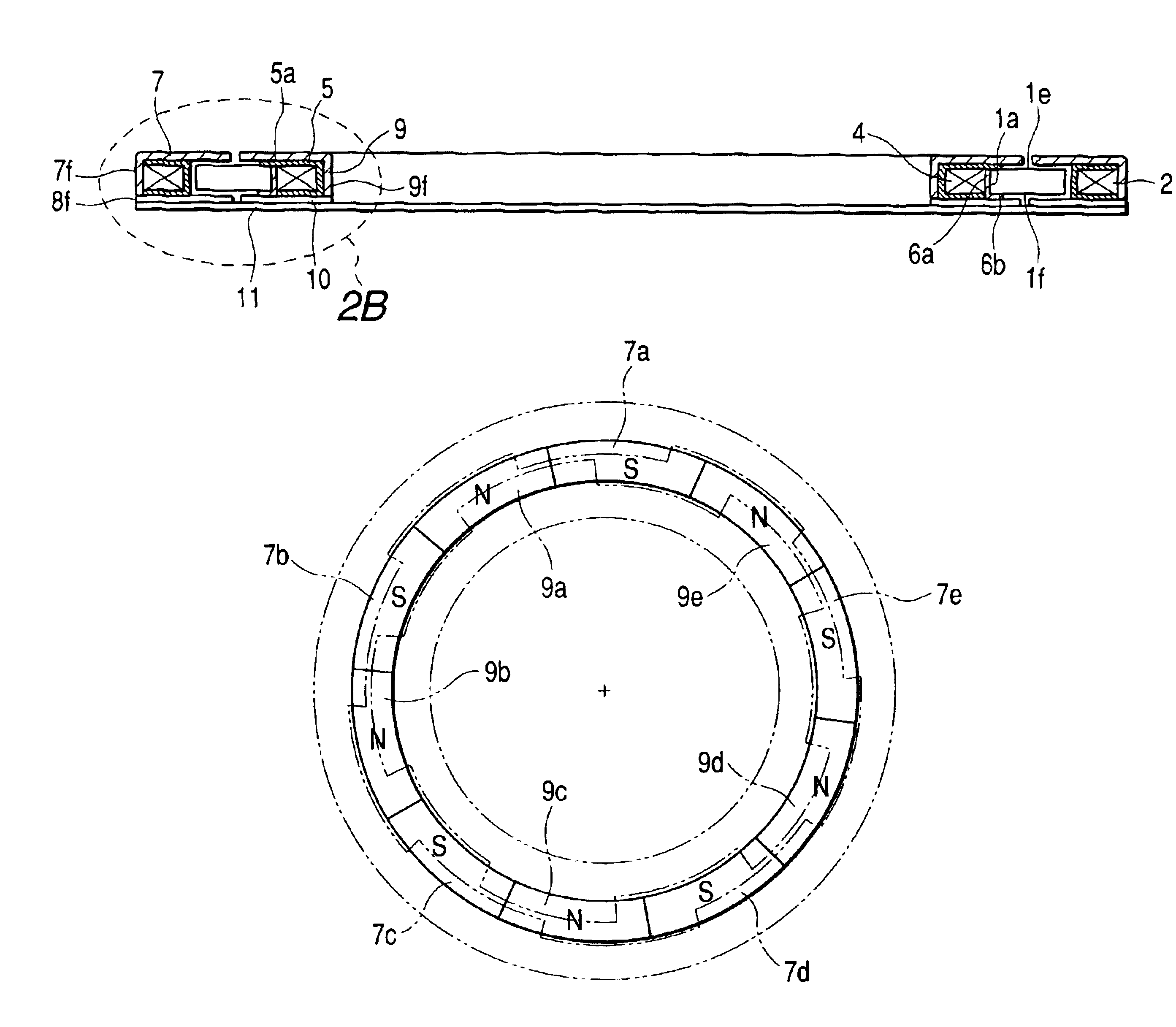
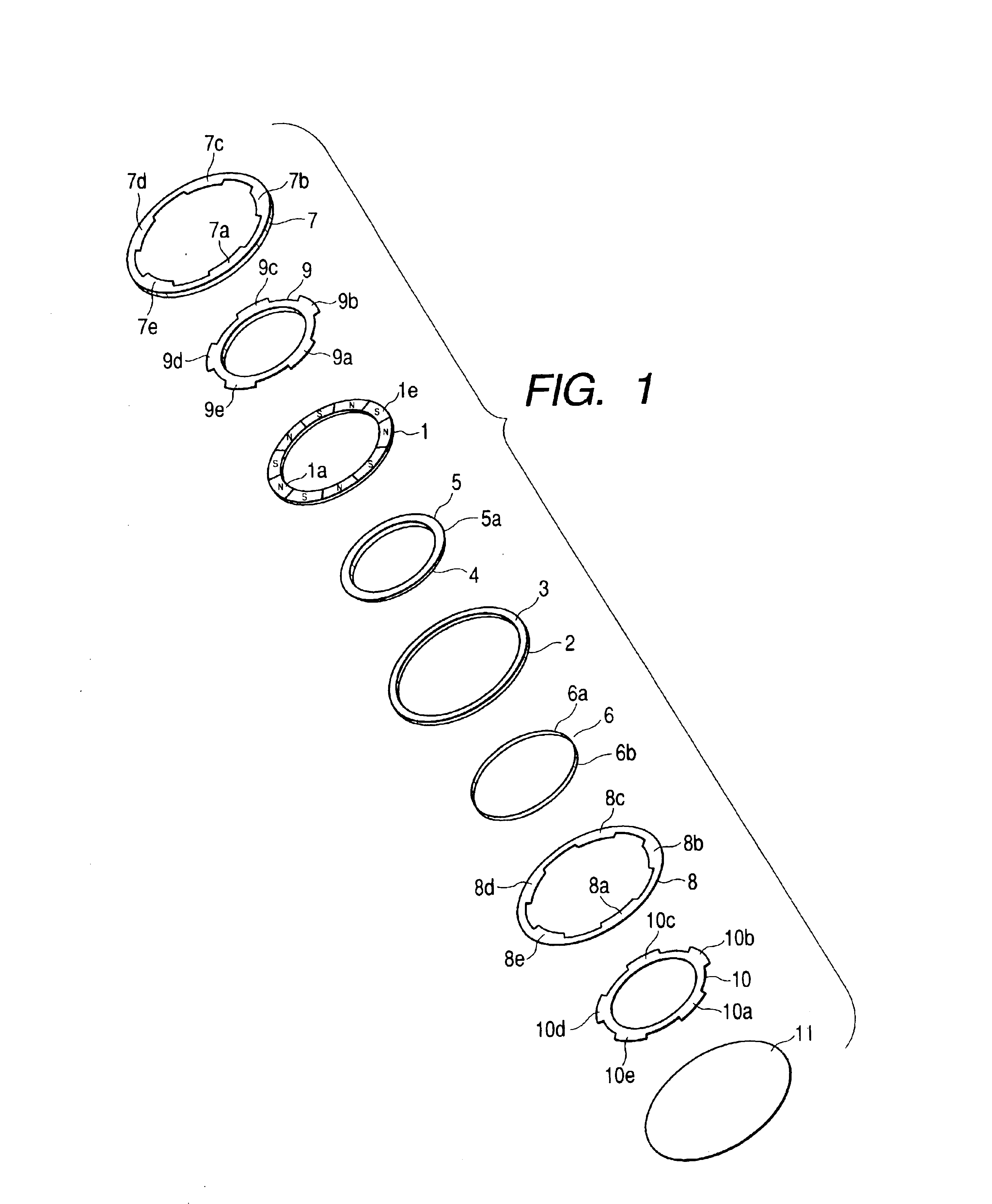
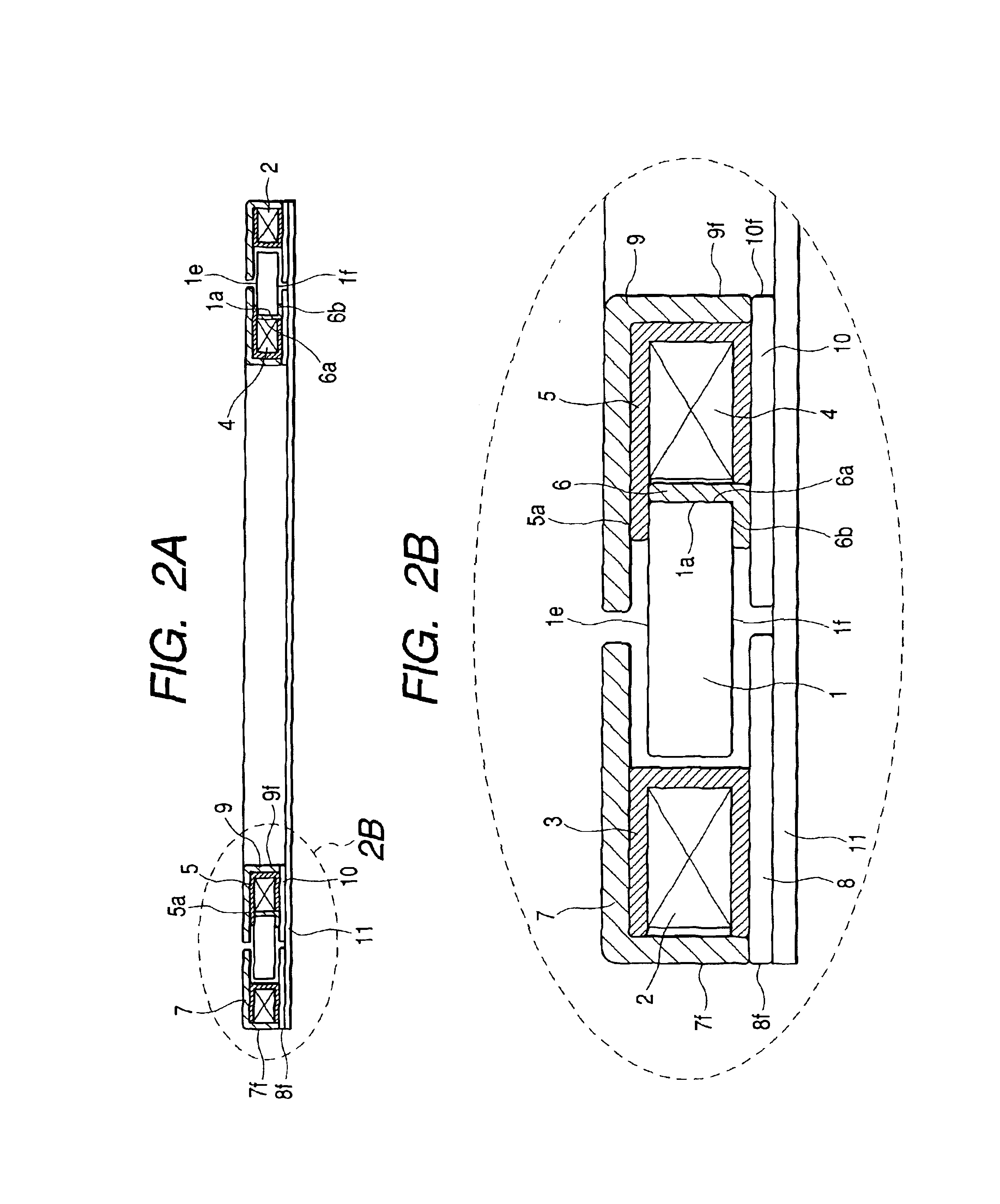
[0041]FIGS. 1 to 6 are views showing a motor according to an embodiment of the present invention. FIG. 1 is an exploded perspective view of the motor. FIG. 2A is a sectional view of a shutter in the axial direction in an assembled state.FIG. 2B is an enlarged view of main part shown in FIG. 2A. FIGS. 3, 4, 5, and 6 are views showing the positional relationship between a stator and a magnet serving as a rotor when the rotor is rotated.

[0042]Referring to FIGS. 1 to 5, a magnet 1 is formed as a rotor. The magnet 1 has a hollow disc shape (ring shape) and is held rotatably regarding the center of the ring as a rotational axis. This magnet has two surfaces 1e and 1f to which the rotational axis of the motor extends as a normal and which oppose each other, an inner peripheral surface, and an outer peripheral surface. At least one of the two surfaces 1e and 1f opposi...


PUM


Abstract

A motor includes a magnet formed into a hollow disc shape and having at least one flat surface circumferentially divided and alternately magnetized to opposite poles, a first coil having an inner peripheral surface opposing the outer peripheral surface of the magnet, a second coil having an outer peripheral surface opposing the inner peripheral surface of the magnet, first magnetic pole portions opposing one flat surface of the magnet, formed from a plurality of teeth extending in the radial direction of the magnet, and excited by the first coil, second magnetic pole portions formed on the opposite side to the first magnetic pole portions via the magnet at positions opposing the first magnetic pole portions, third magnetic pole portions opposing one flat surface of the magnet, formed from a plurality of teeth extending in the radial direction of the magnet, and excited by the second coil, and fourth magnetic pole portions formed on the opposite side to the third magnetic pole portions via the magnet at positions opposing the third magnetic pole portions.

Description

BACKGROUND OF THE INVENTION[0001]1. Field of the Invention[0002]The present invention relates to a flat motor which is thin in the direction of rotating shaft of the rotor.[0003]2. Related Background Art[0004]Brushless motors are suitable for small motors. The brushless motors include a stepping motor of a type shown in FIG. 18.[0005]In this motor, a coil 105 is wound on each of two bobbins 101. The two bobbins 101 are fixed to two stator yokes 106, respectively. In each stator yoke 106, stator teeth 106a and 106b are alternately arranged inside the bobbin 101. Each stator yoke 106 integrated with the stator teeth 106a or 106b is fixed in a case 103 to form a stator 102. A flange 115 and bearing 108 are fixed to one of the two cases 103. Another bearing 108 is fixed to the other case 103. A rotor 109 is formed from a rotor magnet 111 fixed around a rotor shaft 110. The rotor shaft 110 is rotatably supported between the two bearings 108.[0006]In the motor of the type shown in FIG. 18...

Claims


Application Information

Patent Timeline
Patent Type & Authority Patents(United States)
IPC IPC(8): H02K37/14H02K1/27H02K37/12H02K1/14H02K7/06H02K29/00
CPCH02K1/145H02K37/14H02K7/063H02K1/2733H02K29/00
Inventor AOSHIMA, CHIKARA
Owner CANON KK
Why Eureka
Try Eureka