Three-terminal organic electro-luminescent device

a three-terminal, organic technology, applied in the direction of static indicating devices, discharge tubes luminescnet screens, instruments, etc., can solve the problems of low external conversion efficiency, complicated methods for adjusting luminance, and large-scale applications, so as to increase efficiency, increase charge carrier injection, and enhance local electric field

Inactive Publication Date: 2005-05-24
PARK BYOUNG CHOO
View PDF7 Cites 7 Cited by
  • Summary
  • Abstract
  • Description
  • Claims
  • Application Information

AI Technical Summary

Benefits of technology

[0030]The three electrodes are electronically connected to external circuits such that voltages can be applied to the three electrodes, and currents can be drawn in the circuits, either positive or negative, among the three electrodes so as to function as a three-terminal triode. In this device, the electron and hole currents flowing between the first and second electrodes can be controlled and balanced by applying bias...

Problems solved by technology

Thus, the method for adjusting the luminance described above, is more complicate than that employed in another flat panel display such as a liquid crystal display (LCD).
Beside of the complexity for adjusting the luminance, the organic EL diode devices suffer three import...

Method used


Image

  • Three-terminal organic electro-luminescent device
  • Three-terminal organic electro-luminescent device
  • Three-terminal organic electro-luminescent device

Examples


example 1

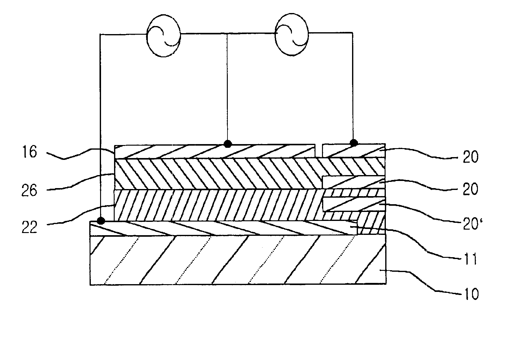
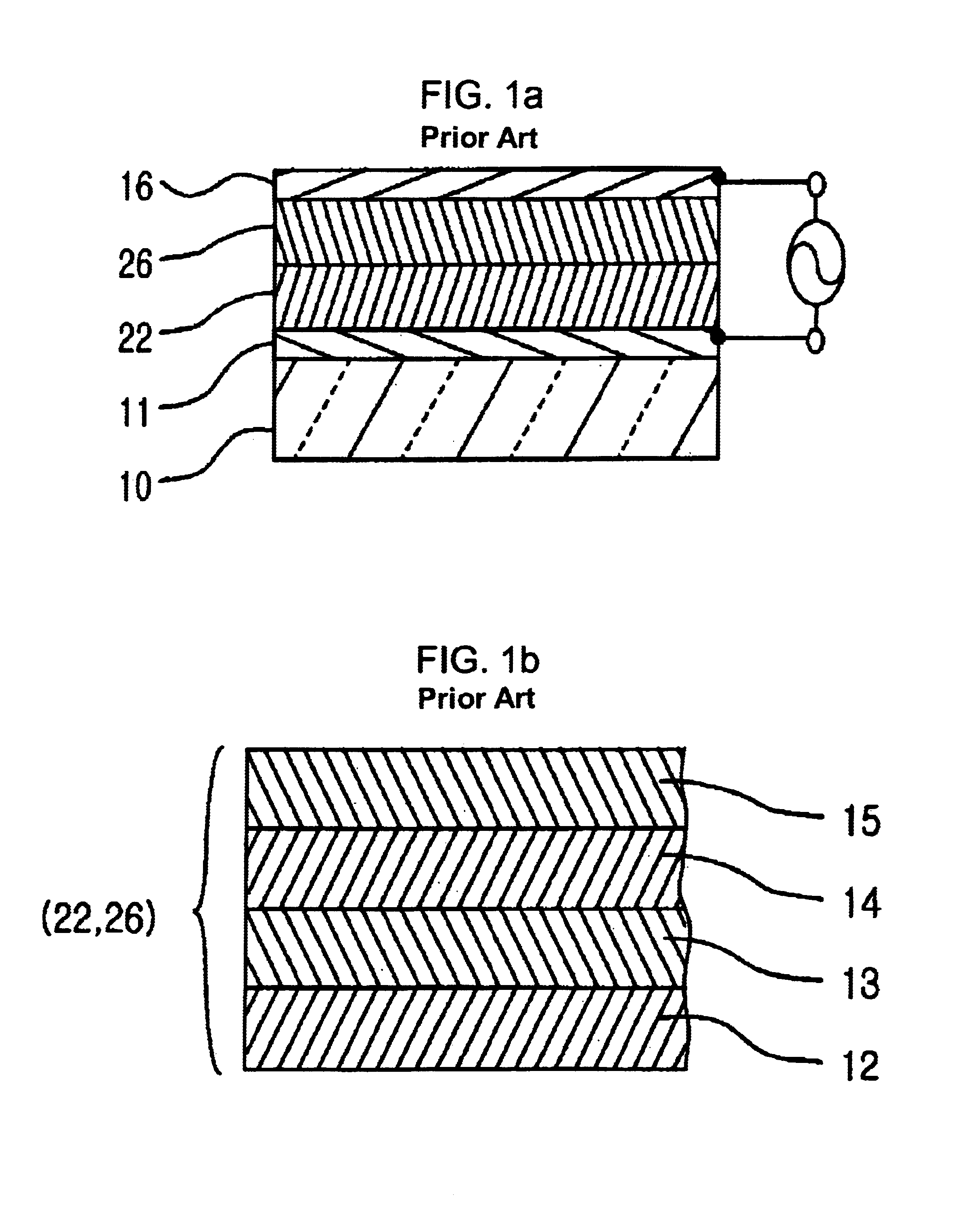
[0086]FIG. 5 is one example of the three-terminal organic EL device in FIG. 4a according to an embodiment of the present invention. As shown in FIG. 5, a three-terminal organic EL device was fabricated, which includes an anode (A) 11 made of ITO, formed on a transparent substrate 10, and organic material layers 22, 26 including a hole injection layer 12 made of m-MTDATA, a hole transporting layer 13 made of α-NPD, a green light-emitting layer 14 made of Alq3, and a electron transporting layer 15 made of Alq3. The organic thin layers were thermally deposited at rate of 0.2 nm / s at 5×10⁻⁵ Torr onto an ITO-coated glass substrate with a sheet resistance of 10-20 ohm / square. The thickness of the hole injection layer, hole transporting layer, the organic emitting layer and the electron injection layer are about 40 nm, 20 nm, 60 nm and 20 nm, respectively. Then, a cathode 16 made of Al—Li compound (1000 nm), is formed on the top of the organic material layers at 5×10⁻⁵ Torr. Beside of the ...

example 2

[0106]FIG. 14 illustrates one example of the three-terminal organic EL device in FIG. 4b according to an embodiment of the present invention. Following FIG. 14, a three-terminal organic EL device was fabricated, which includes an anode (A) 11 made of ITO formed on a transparent substrate 10, and organic material layers 22, 26 including a hole injection layer 12 made of m-MTDATA, a hole transporting layer 13 made of α-NPD, a green light-emitting layer 14 made of Alq3, and a electron transporting layer 15 made of Alq3. The organic thin layers were thermally deposited at rate of 0.2 nm / s at 5×10⁻⁵ Torr onto an ITO-coated glass substrate with a sheet resistance of 10-20 ohm / square. The thickness of the hole injection layer, the hole transporting layer, the organic emitting layer and the electron injection layer are about 40 nm, 20 nm, 60 nm and 20 nm, respectively. Then a cathode 16 made of Al—Li compound (1000 nm), is formed on the top of the organic material layers at 5×10⁻⁵ Torr.

[010...


PUM


Abstract

A three-terminal organic electro-luminescent (EL) device is disclosed for achieving increased efficiency, decreased turn-on voltage, and increased brightness. The three-terminal organic EL device has a first electrode formed on a substrate, at least one organic material layer including an organic light-emitting layer formed on the first electrode, a second electrode formed on the organic material layer; and at least one third electrode formed on or inside said organic material layer. The third electrode is formed outside of a region, which is between the first electrode and the second electrode to prevent a reduction of luminescent area. The luminance of the organic EL device is controlled by adjusting potential of the third electrode with respect to the potentials of the first electrode and the second electrode.

Description

CROSS-REFERENCES TO RELATED APPLICATIONS[0001]This application is a continuation of pending International Patent Application No. PCT / KR02 / 00103 filed Jan. 21, 2002, which designates the United States and claims priority of pending Korean Patent Application No. 2001-0032045 filed on Jun. 8, 2001 and Korean Patent Application No. 2001-0065442 filed on Oct. 23, 2001 in the Korean Intellectual Property Office, the disclosure of which are incorporated herein their entirety by reference.BACKGROUND OF THE INVENTION[0002]1. Field of the Invention[0003]The present invention relates to a three-terminal organic electro-luminescent (EL) device having organic and / or polymeric materials as the luminescent semi-conductive species with a third electrode besides an anode and a cathode and, more particularly, to a three-terminal organic EL device resulting in light-emitting triode (or transistor) structures with increased efficiency, decreased turn-on voltage, and increased brightness, thereby easily...

Claims


Application Information

Patent Timeline
IPC IPC(8): H01L51/52H01L51/50H05B33/26H05B33/02
CPCH01L51/5203H10K50/805
Inventor PARK, BYOUNG CHOO
Owner PARK BYOUNG CHOO
Why Eureka
Try Eureka