Electronic image pickup apparatus

a pickup apparatus and electronic technology, applied in the direction of printers, exposure control, camera focusing arrangement, etc., can solve the problems of increasing production cost, increasing the size of the entire electronic image pickup apparatus, increasing the production cost, etc., and achieving the effect of reducing production cost and down-sizing the apparatus

Inactive Publication Date: 2005-05-24
OLYMPUS CORP
View PDF11 Cites 21 Cited by
  • Summary
  • Abstract
  • Description
  • Claims
  • Application Information

AI Technical Summary

Benefits of technology

[0014]According to the present invention, it is possible to provide an electronic image pickup apparatus for photoelectrically converting a subject image formed by the photographic optical system into image signals by utilizing image pickup devices, and for recording the

Problems solved by technology

Such a construction has caused problems that a number of parts of the whole electronic image pickup apparatus increases and the size of the apparatus itself increases.

Method used


Image

  • Electronic image pickup apparatus
  • Electronic image pickup apparatus
  • Electronic image pickup apparatus

Examples


first embodiment

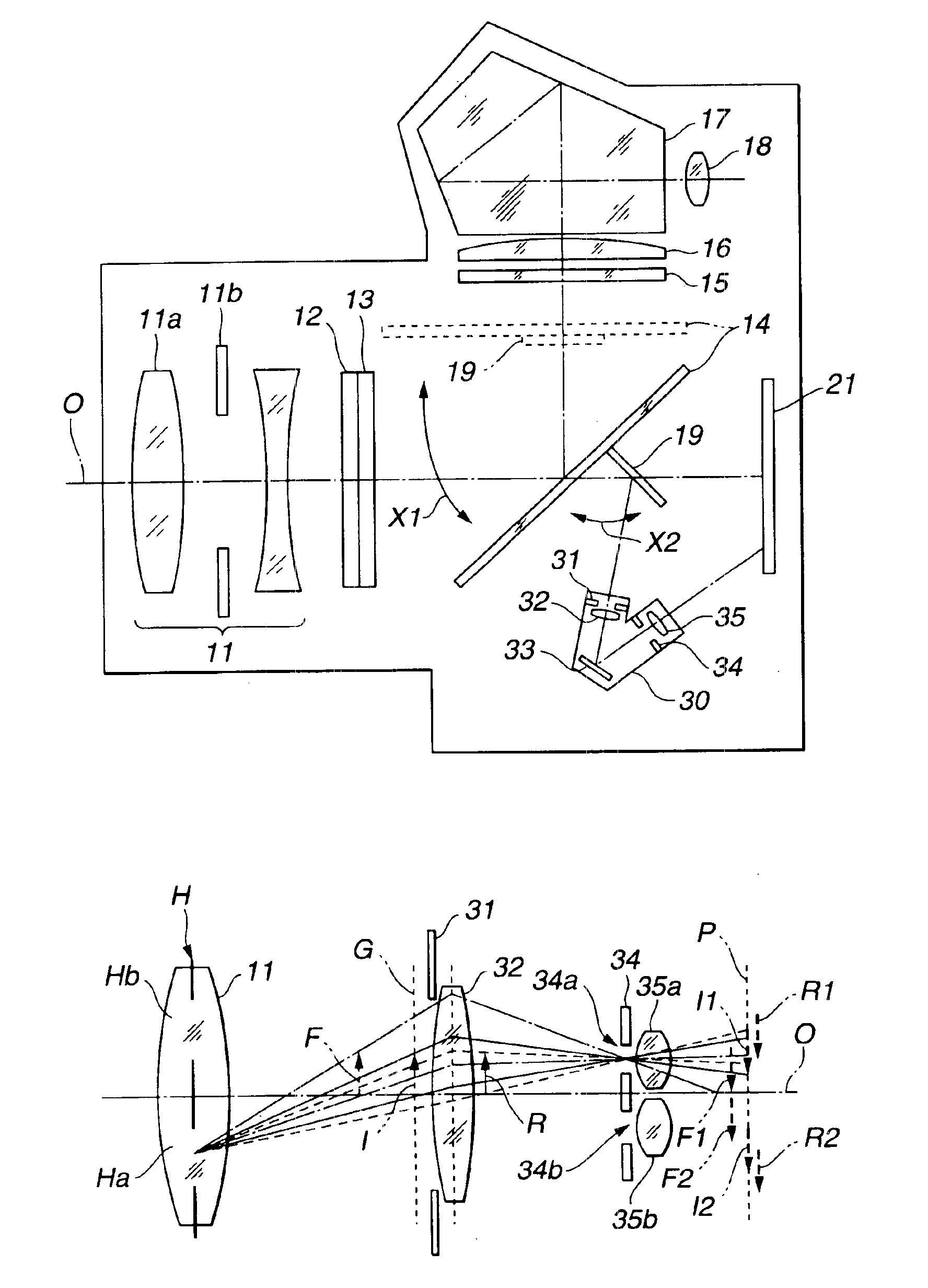
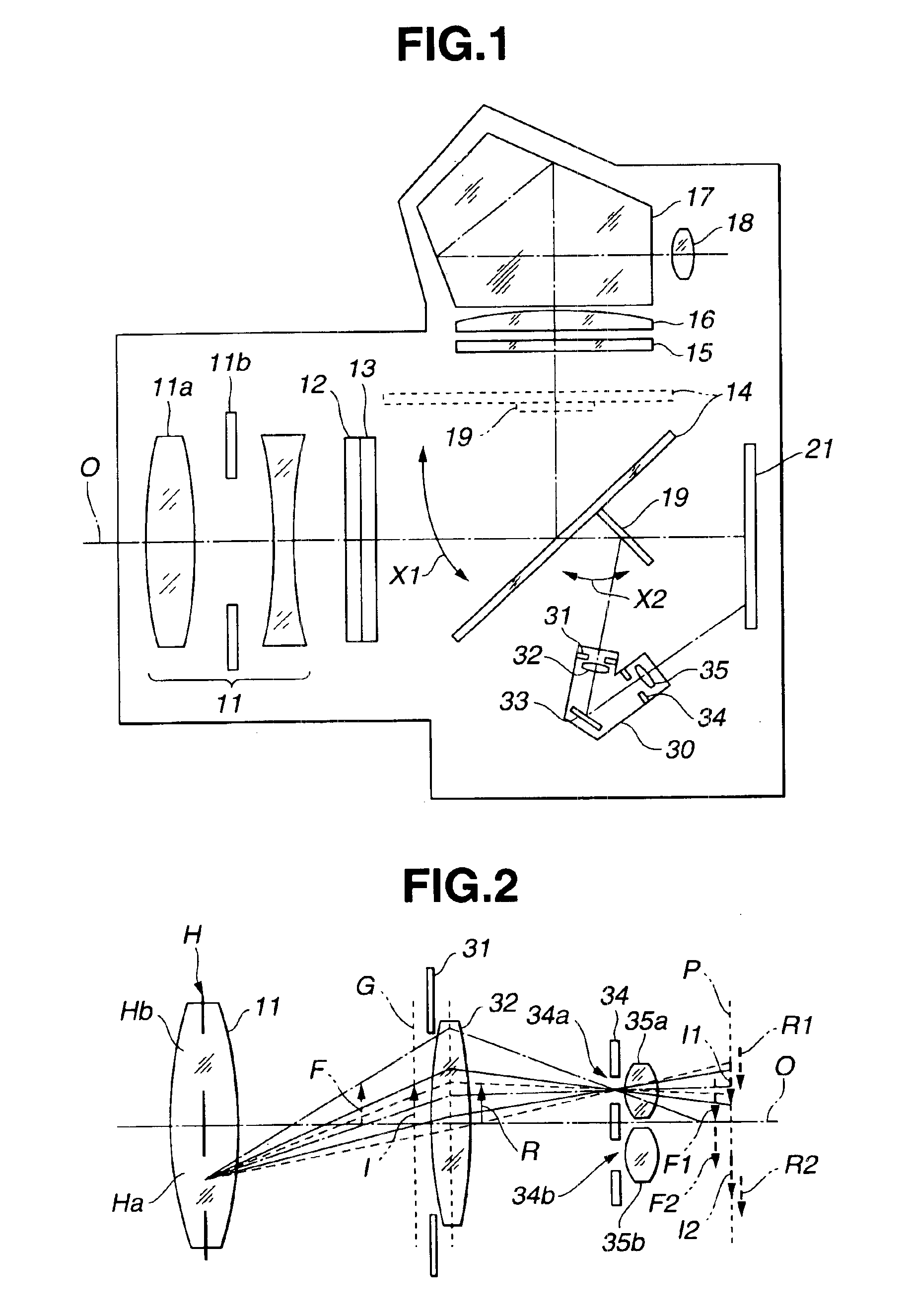
[0037]FIG. 1 is a diagram schematically showing the disposition of the main components of an electronic image pickup apparatus of the invention together with optical paths within the electronic image pickup apparatus of beams which have been transmitted through a photographic optical system. It is noted that FIG. 1 shows only components which are directly related to the invention to simplify the diagram.

[0038]As shown in FIG. 1, a photographic optical system 11 comprising a plurality of lenses and other elements for condensing beams from a subject (hereinafter referred to as subject beams) and for guiding the subject beams to the inside of the electronic image pickup apparatus is disposed at the front side of the electronic image pickup apparatus.

[0039]The photographic optical system 11 comprises an in-focus lens 11a which is a focus adjusting optical system for adjusting the focus by moving in the direction along an optical axis 0 to form the subject image at a predetermined positi...

second embodiment

[0160]Next, the invention will be explained below.

[0161]FIG. 17 is a diagram schematically showing the disposition of the main components of an electronic image pickup apparatus of a second embodiment of the invention together with optical paths within the electronic image pickup apparatus of beams which have been transmitted through a photographic optical system. FIG. 17 corresponds to FIG. 1 in the first embodiment and the components not related to the invention are omitted from the figure to simplify the figure.

[0162]The structure of the electronic image pickup apparatus of the present embodiment is basically the same as that of the first embodiment except for the structure of the focus detecting optical system.

[0163]A focus detecting optical system 130 of the present embodiment comprises a view field mask 131, a field lens 132, a first total reflection mirror 133, a second total reflection mirror 136, a pupil mask 134, and an image reforming lens 135 as shown in FIG. 17. The con...

third embodiment

[0170]Next, the invention will be explained below.

[0171]FIG. 19 is a diagram showing the disposition of the main components of an electronic image pickup apparatus of a third embodiment of the invention together with optical paths within the electronic image pickup apparatus of beams which have been transmitted through the photographic optical system. FIG. 20 is a perspective view showing the concept of the structure of the focus detecting optical system of the electronic image pickup apparatus and conceptually showing the state how the beams of the subject which have been transmitted through the photographic optical system arrive at the image pickup device via a focus detecting optical system 230.

[0172]It is noted that FIG. 19 corresponds to FIG. 1 in the first embodiment and FIG. 20 corresponds to FIG. 3 in the first embodiment. The components not related to the invention are omitted from FIGS. 19 and 20 to simplify the figure.

[0173]The structure of the electronic image pickup app...


PUM


Abstract

An electronic image pickup apparatus comprises a photographic optical system; solid state image pickup devices disposed on a plant where a subject image formed by subject beams which have passed through the photographic optical system is formed; a main mirror disposed between the photographic optical system and the solid state image pickup devices, wherein a part of the main mirror is formed of a half mirror to divide the subject beams which have passed through the photographic optical system into an observing beam and a focus detecting beam; a sub-mirror for reflecting the subject beam which has passed through the part of the main mirror; a focus detecting optical system for forming an image of the subject beam reflected by the sub-mirror on a partial area of the solid image pickup devices; and an electrical circuit for outputting focus detecting information based on image signals of the partial areas of the solid image pickup devices. The structure provides an electronic image pickup apparatus which contributes to the down-sizing of the apparatus and to the reduction of production cost by eliminating an image pickup device which is dedicated for focus detection.

Description

BACKGROUND OF THE INVENTION[0001]1. Field of the Invention[0002]The present invention relates to an electronic image pickup apparatus and more specifically to a focus detecting unit applied to an electronic image pickup apparatus having image pickup devices for generating electrical image signals by photoelectrically converting an optical image of a subject formed by a photographic optical system.[0003]2. Description of the Related Art[0004]Various proposals have been made lately on electronic image pickup apparatuses such as a digital still camera and a digital video camera which are capable of photoelectrically converting an optical image of a subject formed of light beams which have been transmitted through a photographic optical system into electrical signals by utilizing image pickup devices such as CCDs (Charge Coupled Device) and of recording image signals generated therefrom to a recording medium or the like as image data of a predetermined mode.[0005]For instance, Japanese ...

Claims


Application Information

Patent Timeline
IPC IPC(8): G03B3/10G02B7/34G02B7/28G03B13/36H04N5/232
CPCH04N5/23212G02B7/28H04N23/55H04N23/675H04N25/134
Inventor IDE, MASATAKAITO, JUNICHIIMAI, YUJI
Owner OLYMPUS CORP
Why Eureka
Try Eureka