Enhanced heat transfer structure with heat transfer members of variable density

a heat transfer structure and variable density technology, applied in indirect heat exchangers, laminated elements, lighting and heating apparatus, etc., can solve the problems of low heat dissipation efficiency of flat fin geometry heat sinks, failure of devices, and limited heat dissipation capabilities of substrates and base plates, and achieve low susceptibility to clogging and high heat transfer efficiency.

Inactive Publication Date: 2005-05-24
DESSIATOUN SERGUEI V +1
View PDF22 Cites 28 Cited by
  • Summary
  • Abstract
  • Description
  • Claims
  • Application Information

AI Technical Summary

Benefits of technology

[0014]It is therefore an object of the present invention to provide a heat transfer structure capable of highly efficient heat transfer with a low susceptibility to clogging, wherein a plurality of heat transfer members of different density concentration are positioned in a predetermined order so that the density concentration of the heat transfer members increases in the direction of the coolant media flux towards the heat source of the highest temperature.

Problems solved by technology

The heat spreading or dissipation capabilities of the substrate and the base plate are usually limited by the thermal conductivity of the substrate and the base plate material which even in the best case of composites is generally not higher than 600 W / mK.
If the heat sink is unable to remove the high heat flux, the heat spreading resistance adds to the temperature rise of the semiconductor device and thus may lead to the failure of the device.
However, the heat dissipation of flat fin geometry heat sinks are generally low due to the small surface area of the fins and a relatively low heat transfer coefficient.
Therefore, the total thermal resistance built between the heat source and the coolant is disadvantageously high.
As a result, such heat sinks are unable to provide sufficient cooling of modem electronics and other high heat flux sources.
However, these geometries and compositions are not optimal for heat conduction since the heat travels through a relatively long path before rejection to a coolant media.
However, the potential of the heat transfer surface is underused and simultaneously, the pressure drop through the heat transfer structure is generally large.
Therefore, the pressure drops through these heat transfer structures is generally high and the surfaces are susceptible to clogging by particles present in coolant fluid.
Such particles partially clog the heat transfer surface, and cause a decrease in the cross-sections of the flow passages which trap smaller particles in an increasing manner until the coolant fluid flow is substantially blocked.
As is the case in many prior art heat sinks, the heat sink described in U.S. Pat. No. 6,196,307 is susceptible to clogging which occurs on the frontal surfaces of the layers.
Despite the fact that in electronic applications the heat source is usually localized, the layer of highest density beneath or adjacent the heat source cannot be fabricated to exactly correspond to the dimensions of the heat source.
A small portion of the coolant fluid passes in proximity to the heat source, resulting in a nullification of any effects of densification of the structure.
The higher density of the layer causes the decrease of the cross-section of flow passages through the foam layer which undesirably amplifies its susceptibility to clogging.

Method used


Image

  • Enhanced heat transfer structure with heat transfer members of variable density
  • Enhanced heat transfer structure with heat transfer members of variable density
  • Enhanced heat transfer structure with heat transfer members of variable density

Examples


Embodiment Construction

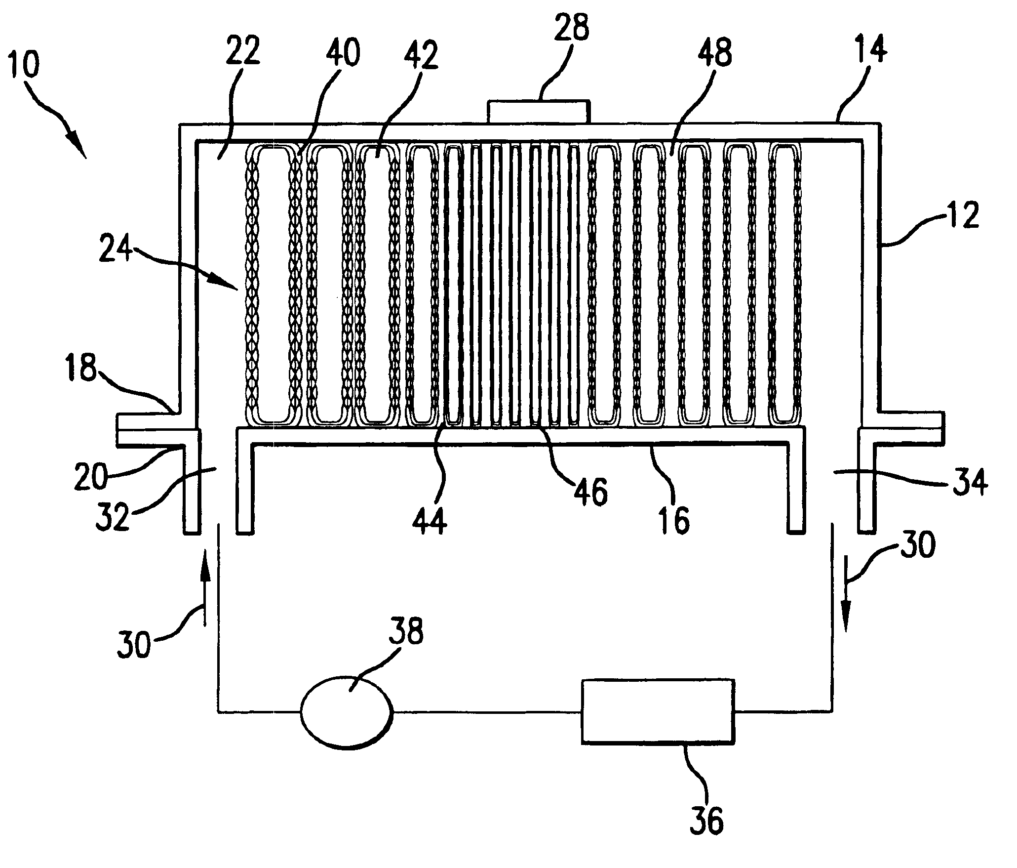
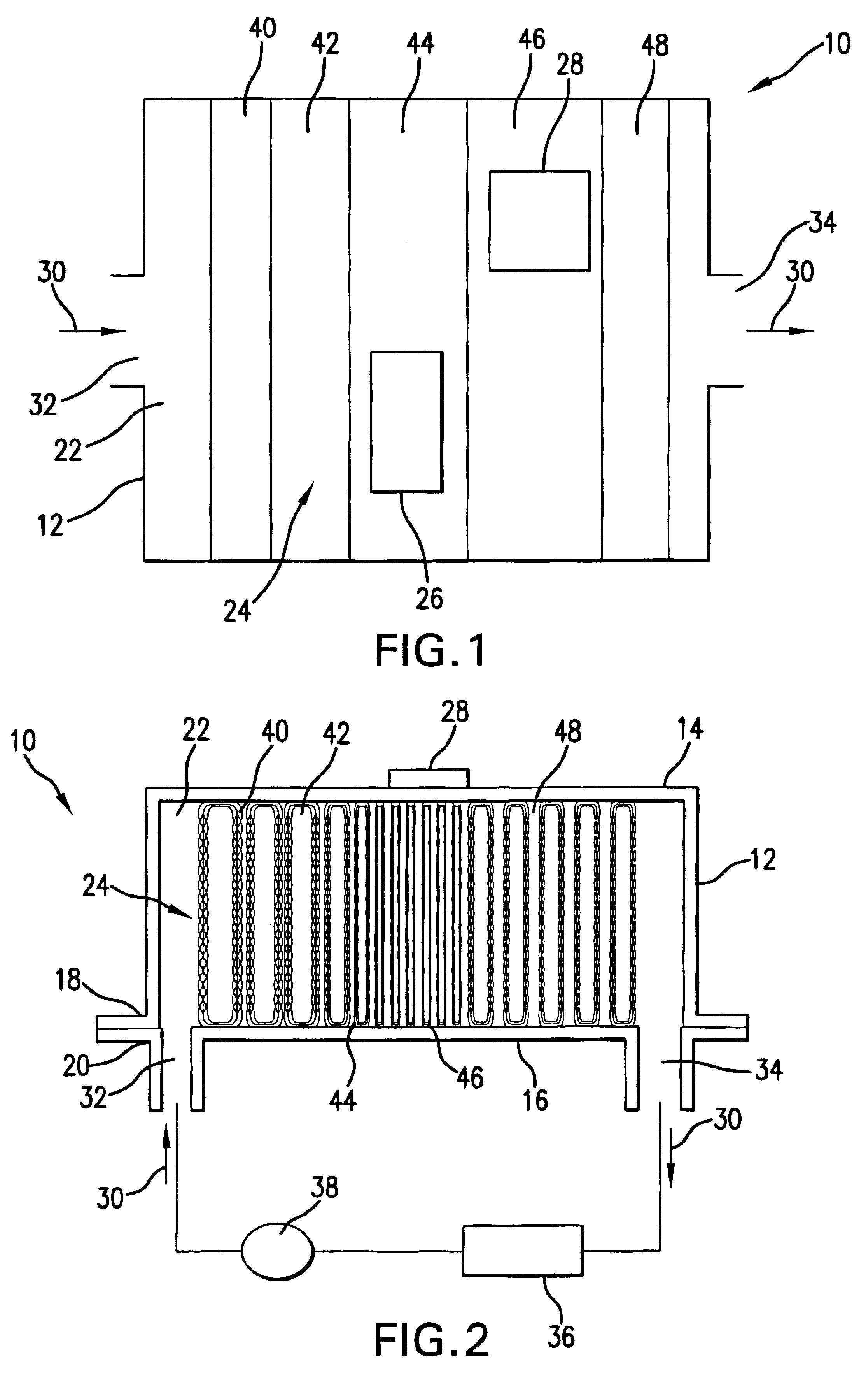
[0050]Referring to FIGS. 1 and 2, a heat transfer structure 10 is shown which includes a heat transfer module 12 having module walls 14 and 16 attached or fastened each to the other. For purposes of illustration, fastening of the walls 14 and 16 may be secured at perimeters 18 and 20 thus forming a duct chamber 22 therebetween. A plurality of heat transfer members, for example, in the form of perpendicularly directed pin fins 24 are positioned in the duct chamber 22 and extend between the module walls 14 and 16. Localized heat sources 26 and 28 represent heat generating semiconductor structures which are attached to the module wall 14 and are in thermal contact therewith.

[0051]A coolant media 30 is supplied to the inlet port 32 into the heat transfer module 12 and exits from the outlet port 34 thereof. The entry coolant media ingressing or being charged into the heat transfer module 12 is at a substantially lower temperature than the heat sources 26 and 28. The cooling media absorbs...


PUM


Abstract

A heat transfer structure includes a heat transfer module having a plurality of heat transfer members in the duct chamber with the density increased in the direction of the flow of the coolant and having a greatest density adjacent to the position of a heat source attached in thermal contact with the heat transfer module. The profile of the duct chamber is adjusted to the position of the heat source to increase the velocity of coolant directly under the heat source and to partially or completely block the coolant flow to the areas which do not need to be temperature adjusted. The heat transfer members may be formed as pin fins fabricated from springs compressed to a predetermined density in a direction perpendicular to the longitudinal axis of the spring (and/or in parallel to the longitudinal axis of the heat transfer module).

Description

REFERENCE TO RELATED APPLICATIONS[0001]This Utility Patent Application is based on Provisional Patent Application Ser. No. 60 / 378,965, filed on May 10, 2002.FIELD OF THE INVENTION[0002]The present invention relates to heat transfer structures and methods of transporting heat. More in particular, this invention pertains to heat transfer structures for cooling electronics and other heat generating devices.[0003]Still further, the subject invention pertains to heat transfer structures which use the concept of variable density heat transfer members, for example pin fins, within the heat transfer structure to promote efficient thermal transport.BACKGROUND OF THE INVENTION[0004]In order to improve power and speed of electronics, while simultaneously decreasing the size of electronic devices, efforts have been made to develop efficient ways to dissipate heat generated by electronic devices. Heat flux of 100W / cm2 and higher in semiconductor elements are standard in any applications of elect...

Claims


Application Information

Patent Timeline
Patent Type & Authority Patents(United States)
IPC IPC(8): H01L23/473H01L23/427H01L23/34H05K7/20
CPCH01L23/427H01L23/473H01L2924/0002H01L2924/00
Inventor DESSIATOUN, SERGUEI V.IVAKHNENKO, IGOR
Owner DESSIATOUN SERGUEI V
Why Eureka
Try Eureka