Bidirectional VSC converter with a resonant circuit

Inactive Publication Date: 2005-05-24
ABB (SCHWEIZ) AG
View PDF12 Cites 42 Cited by
  • Summary
  • Abstract
  • Description
  • Claims
  • Application Information

AI Technical Summary

Benefits of technology

[0012]According to a further preferred embodiment of the invention, the ARCP-circuit comprises an auxiliary valve comprising several series connected sets of auxiliary valve circuits, where each set comprises two series connected auxiliary valve circuits, each of which comprising a semiconductor component of turn-off type and a rectifying component connected in anti-parallel therewith, the semiconductor components of turn-off type in the two auxiliary valve circuits in one and the same set being arranged in opposite polarity in relation to each other. By making the ARCP-circuit comprising several sets of auxiliary valve circuits in this manner, instead of one single set as conventional, it will in a simple manner be possible to adapt the ARCP-circuit in dependence of the desired characteristics of the converter.
[0013]According to a further preferred embodiment of the invention, the ARCP-circuit comprises several series connected partial circuits, each of which comprising a set of auxiliary valve circuits connected in s

Problems solved by technology

The resonance circuit is also used in connection with turn-off of the semiconductor components in the current valves when t

Method used


Image

  • Bidirectional VSC converter with a resonant circuit
  • Bidirectional VSC converter with a resonant circuit
  • Bidirectional VSC converter with a resonant circuit

Examples


Embodiment Construction

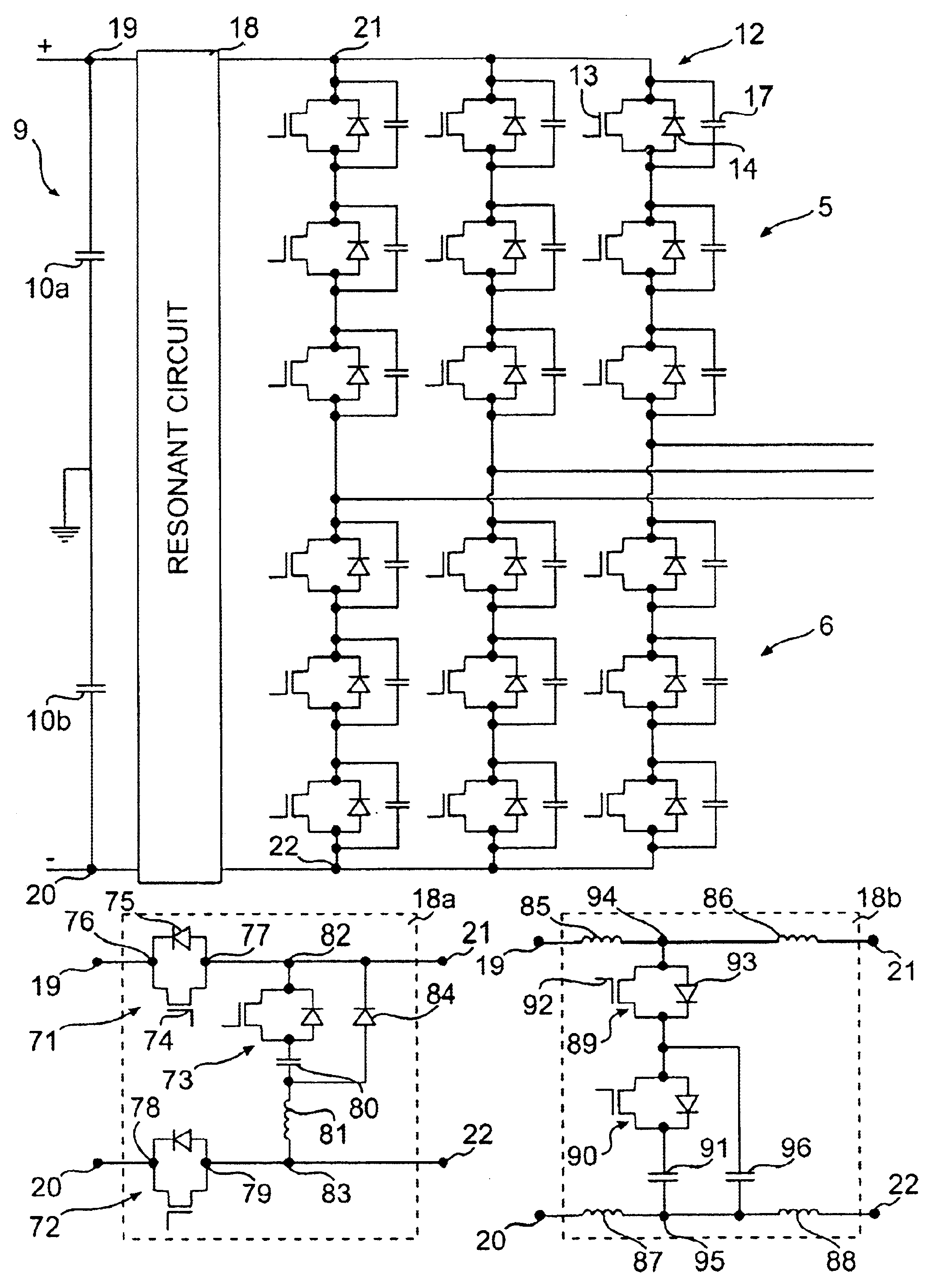
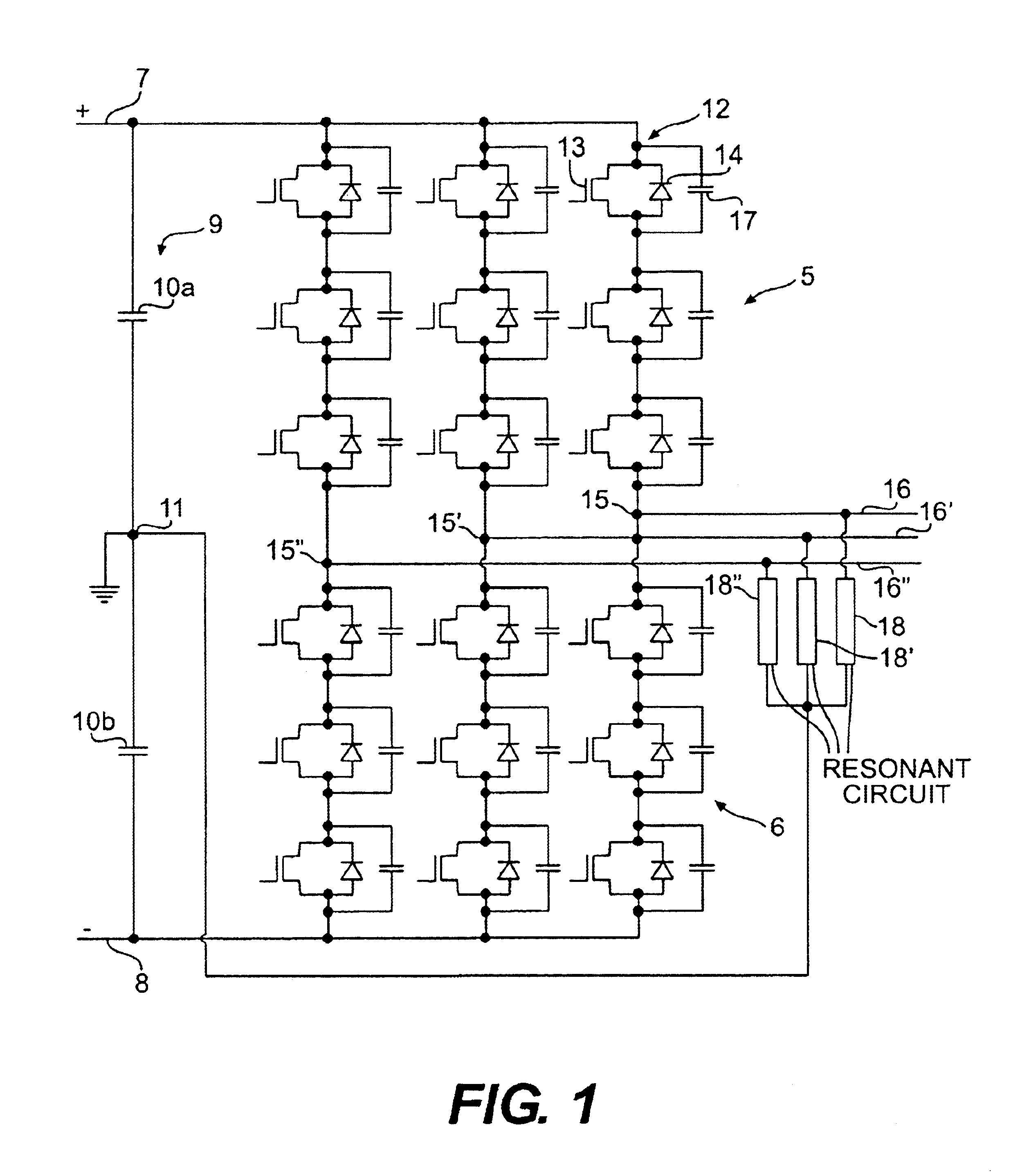
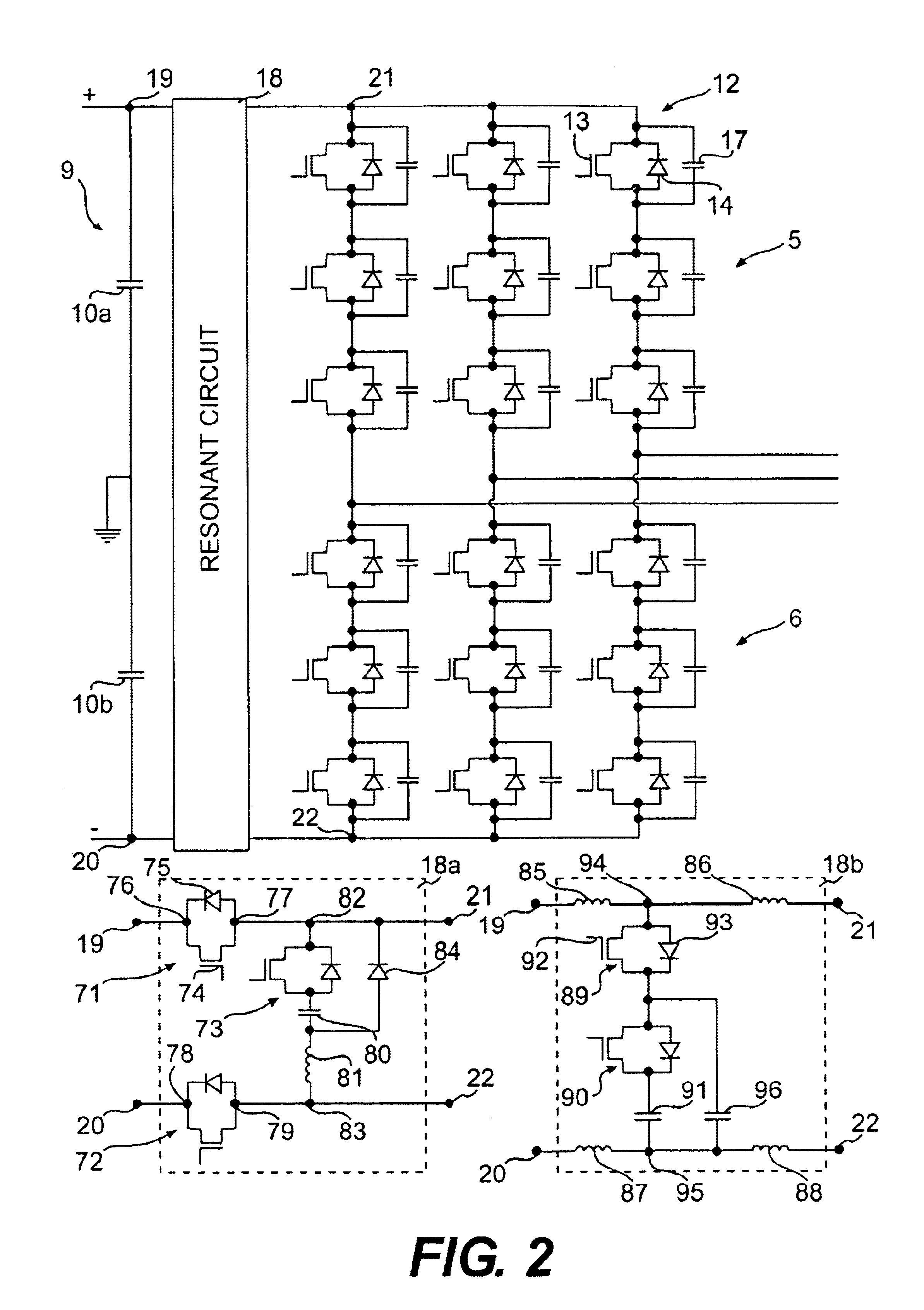
[0024]FIGS. 1 and 2 schematically illustrate two alternative embodiments of a VSC-converter 1 according to the invention. The converter is here provided with three so-called phase legs 2-4 and is consequently adapted for a three-phase alternating voltage network. This type of assemblage with three-phase legs is normally denominated three-phase bridge. The VSC-converter could however also be adapted for an alternating voltage network having more as well as fewer phases than three. It could for instance be adapted for a single phase alternating voltage network and would in such a case only have one phase leg of the type in question.

[0025]Each phase leg 2-4 of the VSC-converter illustrated in FIGS. 1 and 2 has two current valves 5, 6 connected in series between the two poles 7, 8 of a direct voltage side of the converter. A capacitor circuit 9 comprising at least one so-called intermediate link capacitor is arranged between the two poles 7, 8. In the converter illustrated in FIGS. 1 an...


PUM


Abstract

The invention relates to a VSC-converter for converting direct voltage into auxiliary voltage and vice versa, which comprises a series connection of at least two current valves (5, 6) arranged between two poles (7, 8), a positive and a negative, of a direct voltage side of the converter, each current valve comprising several series connected circuits (12), each of which circuits comprising a semiconductor component (13) of turn-off type and a rectifying component (14) connected in anti-parallel therewith, an alternating voltage phase line (16) being connected to a midpoint (15), denominated phase output, of the series connection of current valves (5, 6) between two of said current valves while dividing the series connection into two equal parts. Each of the series connected circuits (12) of the respective current valve comprises, in order to make possible a good voltage distribution between the semiconductor components (13) of turn-off type included in the respective current valve, a snubber capacitor (17) connected in parallel with the semiconductor component (13) of turn-off type included in the circuit. The converter (1) further comprises a resonance circuit (18) for recharging the snubber capacitors (17) of the current valves.

Description

FIELD OF THE INVENTION AND PRIOR ART[0001]The present invention relates to a VSC-converter according to the preamble of the subsequent claim 1.[0002]A VSC-converter for connection between a direct voltage net-work and an alternating voltage network is previously known e.g. from the thesis “PWM and control of two and three level High Power Voltage Source Converters” by Anders Lindberg, Royal Institute of Technology, Stockholm, 1995, in which publication a plant for transmitting electric power through a direct voltage network for high-voltage direct current (HVDC), while utilizing such converters, is described. Before the creation of this thesis, plants for transmitting electric power between a direct voltage network and an alternating voltage network have been based upon the use of network commutated CSC(Current Source Converter)-converters in stations for power transmission. However, in this thesis a totally new concept is described, which is based on instead using VSC(Voltage Sourc...

Claims


Application Information

Patent Timeline
IPC IPC(8): H02M7/48H02M7/12
CPCH02M7/48H02M7/4826
Inventor BIJLENGA, BOASPLUND, GUNNARLUNDBERG, PETERJONSSON, TOMASJOHANSSON, NIKLASNORRGA, STAFFAN
Owner ABB (SCHWEIZ) AG
Why Eureka
Try Eureka