Blood processing systems and methods

a centrifuge and processing system technology, applied in the direction of centrifugal force sediment separation, feed/discharge of settling tanks, other blood circulation devices, etc., can solve the problems of time-consuming and laborious loading and unloading operations, inconvenient handling, and inconvenient handling. , to achieve the effect of convenient handling

Inactive Publication Date: 2005-05-31
FENWAL
View PDF131 Cites 43 Cited by
  • Summary
  • Abstract
  • Description
  • Claims
  • Application Information

AI Technical Summary

Benefits of technology

[0009]The invention provides improved blood processing systems and methods that create unique dynamic flow conditions within a compact, easily handled processing chamber.

Problems solved by technology

Conventional centrifuges often do not permit easy access to the areas where the disposable systems reside during use.
As a result, loading and unloading operations can be time consuming and tedious.
However, this approach is often counterproductive, as it increases the cost of the disposables.

Method used


Image

  • Blood processing systems and methods
  • Blood processing systems and methods
  • Blood processing systems and methods

Examples


example 1

[0138]A study compared the conventional 200 ml A-35 chamber to the 30 ml, reduced depth chamber described above (which will be called the “30 ml Chamber”). Both chambers had a collection area of 160 cm2.

[0139]The study used a paired run protocol. During the protocol, 59 normal donors underwent a platelet collection procedure with the A-35 chamber. The same donors underwent another platelet collection procedure with the 30 ml Chamber. The order of the collection procedures was randomized among the donors, with the procedures performed about a month apart.

[0140]Both procedures were conducted on a CS-3000® Centrifuge operated at a speed of 1600 RPM. All operating parameters for the first procedure were repeated in the second procedure. Six different blood centers participated in the study.

[0141]The results were correlated and statistically verified.

[0142]The study showed that the 30 ml Chamber provided significantly improved platelet collection. Compared to the A-35 Chamber, the 30 ml ...

example 2

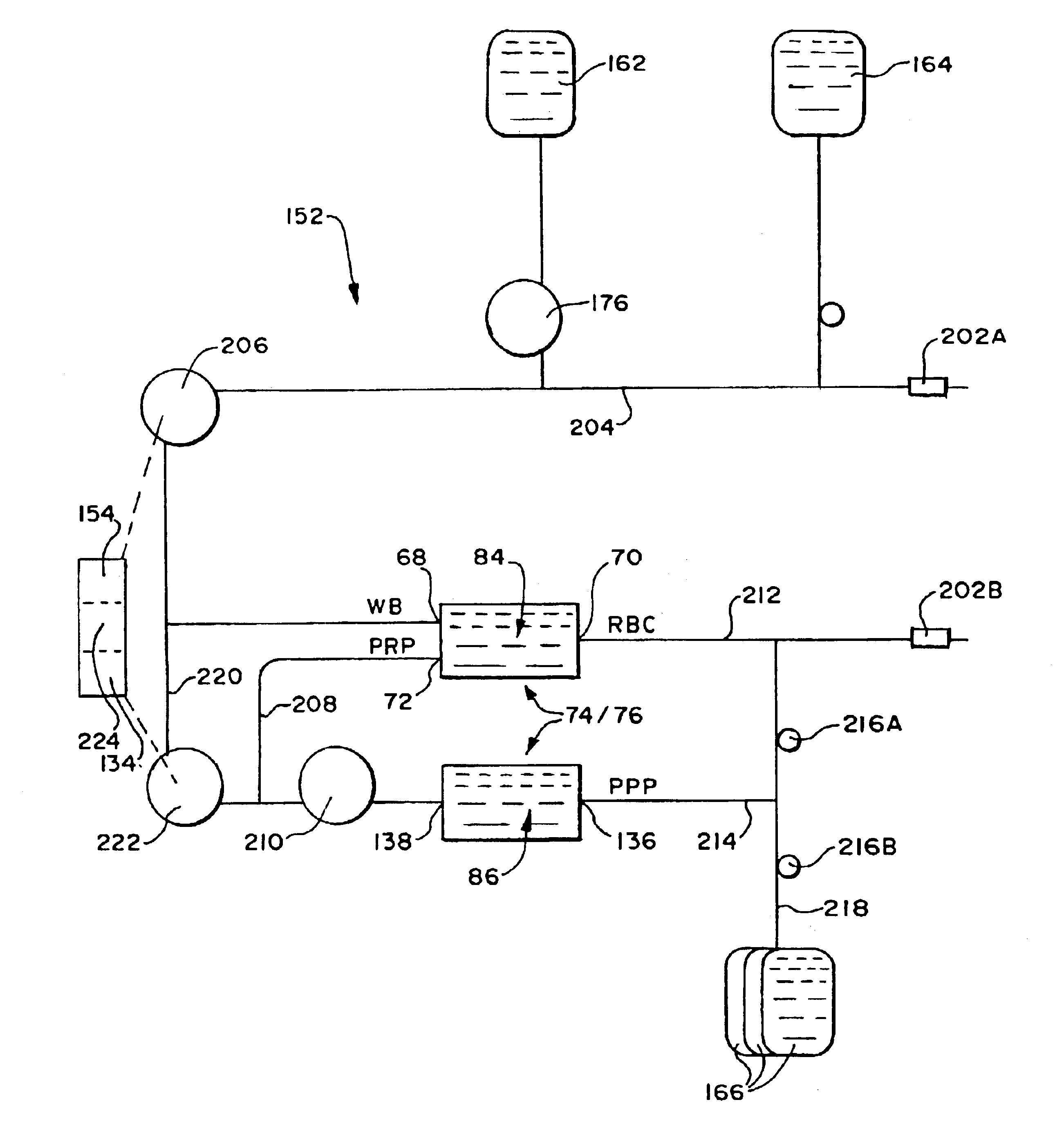
[0287]A study evaluated a two stage separation chamber 74 like that shown in FIG. 16 in a platelet collection procedure on a healthy human donor. The chamber 74 was part of a double needle system 152, like that shown in 28. The system 152 recirculated PRP in the manner shown in FIG. 28 to obtain a hematocrit of 32.1% in the PRP collection region 124 of the chamber 74.

[0288]In this study, the low-G wall 64 of the first stage chamber 84 was not tapered in the direction of circumferential flow from the PRP collection region 124. The low-G wall 64 was isoradial along the circumferential flow path in the first stage chamber 84, except for the presence of a RBC barrier 128, which stepped into the chamber across the RBC collection passage, as shown in FIG. 17. The low-G wall 64 was isoradial along the entire circumferential flow path of the second chamber 86.

[0289]FIG. 35A shows the platelet count sampled in the PRP (in 1000 platelets per uL) over time during the 45 minute procedure. As th...

example 3

[0295]Another study evaluated a two stage separation chamber like that in Example 2 in a platelet collection procedure on a healthy human donor. As in Example 2, a double needle system was used. The system recirculated PRP to obtain an inlet hematocrit of 34.3%.

[0296]In this study, the low-G wall 64 of the first stage chamber 84 was tapered in the direction of circumferential flow from the PRP collection region 124, like that shown in FIG. 17. The low-G wall 64 also included RBC barrier 128 like that shown in FIG. 17. The low-G wall 64 was also tapered along the entire circumferential flow path of the second chamber 86.

[0297]FIG. 36A shows the platelet count sampled in the PRP (in 1000 platelets per uL) over time during the 45 minute procedure. As there shown, a platelet count of 300 was achieved in the first 5 minutes of the procedure. The platelet count peaked at 331 after 21 minutes. At the end of the procedure, the platelet count was 302.

[0298]FIG. 36B shows the physical size of...


PUM

PropertyMeasurementUnit
volumeaaaaaaaaaa
depthaaaaaaaaaa
volumeaaaaaaaaaa

Abstract

Systems and methods centrifugally separate whole blood into red blood cells, plasma, and a platelet concentrate. The systems and methods rotate a first rotating separation zone about a rotational axis, to separate whole blood into red blood cells and plasma constituent carrying platelets. Red blood cells separated are directed in a first circumferential flow direction toward a terminal wall, where blood flow is halted. Surface hematocrit is successively increased in the first circumferential flow direction by separating the plasma constituent from the red blood cells. Separated red blood cells are directed from the first rotating separation zone through a path where the surface hematocrit is the most. Plasma constituent separated is directed in a second circumferential flow direction opposite to the first circumferential flow direction toward a different region in the first rotating separation zone, where the surface hematocrit is the least. The systems and methods separate the plasma constituent into platelet concentrate and plasma in a second rotating separation zone.

Description

RELATED APPLICATIONS[0001]This application is a divisional of co-pending U.S. patent application Ser. No. 09 / 661,331, filed Sep. 13, 2000 (now U.S. Pat. No. 6,511,411), entitled “Compact Enhanced Yield Blood Processing Systems,” which is a divisional of U.S. patent application Ser. No. 08 / 856,096, filed May 14, 1997 (now U.S. Pat. No. 6,228,017), which is a divisional of U.S. patent application Ser. No. 08 / 146,403 filed Nov. 1, 1993 (now U.S. Pat. No. 5,656,163), which is a continuation of U.S. patent application Ser. No. 07 / 964,771, filed Oct. 22, 1992 (now abandoned).FIELD OF THE INVENTION[0002]The invention relates to centrifugal processing systems and apparatus.BACKGROUND OF THE INVENTION[0003]Today blood collection organizations routinely separate whole blood by centrifugation into its various therapeutic components, such as red blood cells, platelets, and plasma.[0004]Conventional blood processing systems and methods use durable centrifuge equipment in association with single ...

Claims


Application Information

Patent Timeline
Patent Type & Authority Patents(United States)
IPC IPC(8): A61M1/36B01D21/26B04B5/00B04B5/04B04B13/00A61M1/02A61M1/30B01D17/02B01D21/24B04B7/08
CPCA61M1/3696A61M1/3693B01D17/0217B01D21/0003B01D21/2405B01D21/245B01D21/262B01D21/30B04B5/0442B04B7/08B04B13/00A61M1/3603A61M1/308A61M1/303A61M1/302B01D21/26A61M1/025A61M2202/0427A61M2205/331A61M2205/3344A61M2205/3351A61M2205/3355A61M2205/3393B01D2221/10B04B2005/045A61M1/30A61M2202/0071B01D21/32B01D21/34B04B2013/006
Inventor BROWN, RICHARD I
Owner FENWAL
Why Eureka
Try Eureka