Magnetic media with improved exchange coupling

a technology of exchange coupling and magnetic media, which is applied in the field of magnetic recording media, can solve the problems of increasing the amount of time required, reducing the mrt in the medium, and reducing the thermal stability of the layer b>4, so as to facilitate the rapid switching of the lower magnetic layer, facilitate the effect of reducing coercivity and good thermal stability

Inactive Publication Date: 2005-05-31
WESTERN DIGITAL TECH INC
View PDF34 Cites 88 Cited by
  • Summary
  • Abstract
  • Description
  • Claims
  • Application Information

AI Technical Summary

Benefits of technology

[0012]Hc of the lower magnetic layer is greater than or equal to zero but less than the exchange field Hex at recording switching times. The He of the lower magnetic layer at recording switching times is typically less than or equal to about one half of the exchange field for recording times. This facilitates quickly switching the lower magnetic layer to its desired magnetization direction. (The Hc of the upper magnetic layer at recording switching times is typically substantially greater than the Hc of the lower magnetic layer at recording switching times.)
[0013]In accordance with another feature of the invention, the anisotropy constant Ku of the upper magnetic layer is greater than 0.5×10⁶ ergs / cm3 to provide good thermal stability. In one embodiment, the Ku of the upper layer is greater than 1.0×10⁶ ergs / cm3. (The Ku of the upper magnetic layer should not be so high as to hamper writing, and is typically less than 107 ergs / cm3.) The Ku of the lower layer can be smaller than the Ku of the upper layer. For example, the lower magnetic layer can have a Ku of 1.0×10⁴ ergs / cm3, 1.0×10³ ergs / cm3, or even lower (but greater than or equal to 0 ergs / cm3). (A lower Ku for the lower magnetic layer facilitates a lower coercivity, which in turn facilitates ease of switching the magnetization direction of the lower magnetic layer.)

Problems solved by technology

Unfortunately, reducing MrT in medium 1 reduces the thermal stability of layer 4.
Weak coupling between layers 26 and 30 is disadvantageous because it increases the amount of time required to switch the state of medium 20 to an antiferromagnetic state.

Method used


Image

  • Magnetic media with improved exchange coupling
  • Magnetic media with improved exchange coupling
  • Magnetic media with improved exchange coupling

Examples


Embodiment Construction

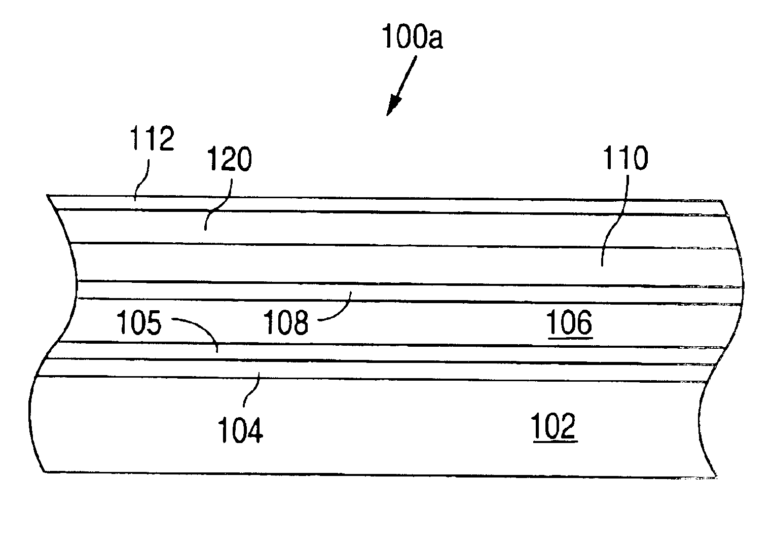
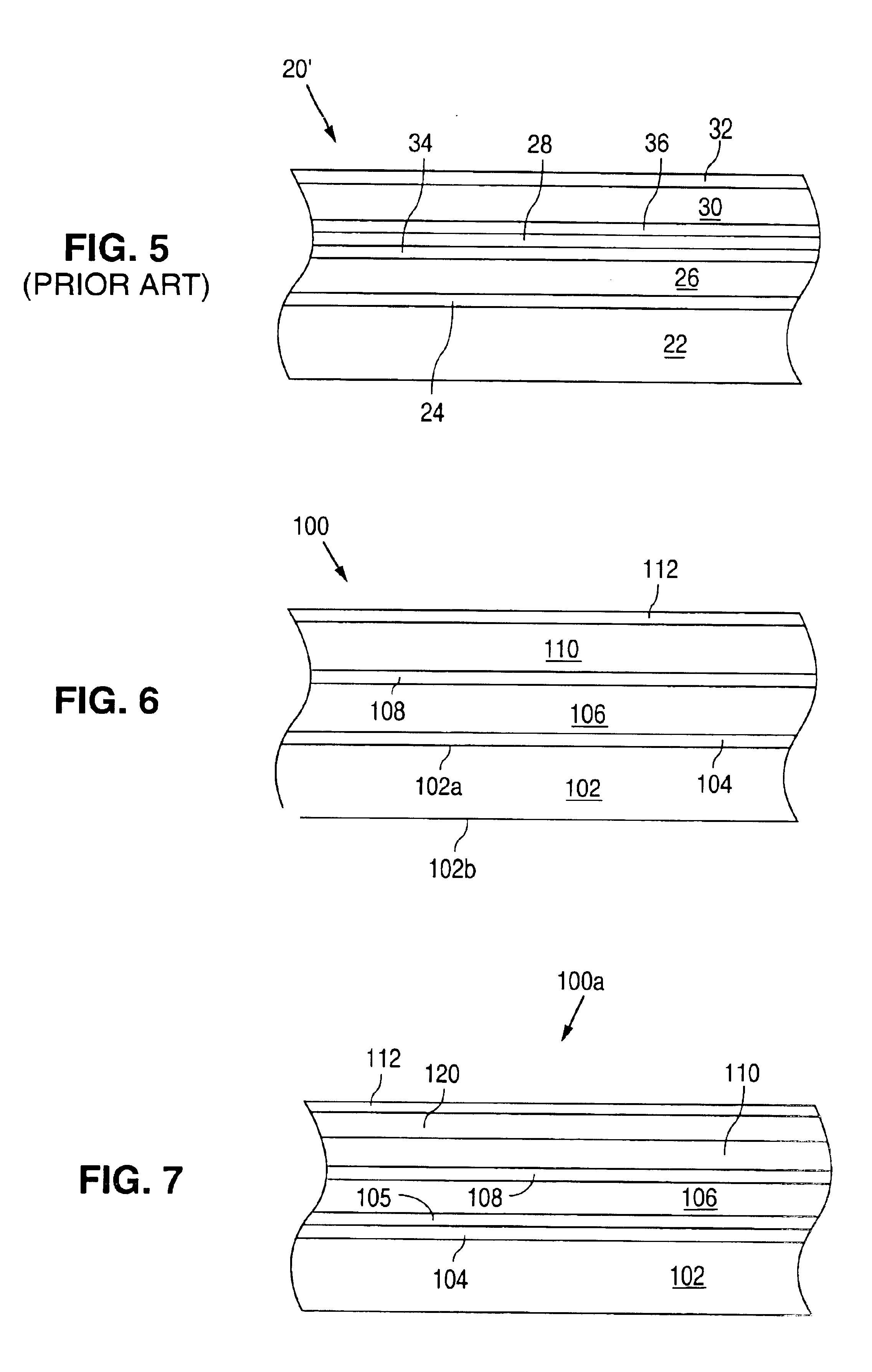
[0032]Referring to FIG. 6, a magnetic recording medium 100 in accordance with the invention comprises a non-magnetic substrate 102, an underlayer 104, a lower magnetic layer 106, an intermediate layer 108, an upper magnetic layer 110 and a carbon protective overcoat 112. Substrate 102 can be an aluminum alloy substrate coated with an electroless plated nickel-phosphorus alloy. Alternatively, substrate 102 can be glass, glass-ceramic, or other appropriate material. (Typically, the above-mentioned layers are formed on both the top and bottom surfaces 102a, 102b of substrate 102, but only the layers on top surface 102a are shown for ease of illustration.)

[0033]Magnetic layers 106 and 110 are typically Co, Fe or Ni-based alloys. Layer 106 is typically between 2 and 8 nm thick, and layer 110 is typically 6 to 30 nm thick. Intermediate layer 108 is typically Ru or a Ru alloy (e.g. consisting essentially of Ru). (Layer 108 is typically between 0.3 and 1.0 nm thick.) For the case of Co allo...


PUM

PropertyMeasurementUnit
thicknessaaaaaaaaaa
thickaaaaaaaaaa
thickaaaaaaaaaa

Abstract

A magnetic recording medium includes a substrate, an underlayer, a lower magnetic layer formed on the underlayer, an intermediate layer, and an upper magnetic layer formed on the intermediate layer. The intermediate layer is typically Ru, and promotes antiferromagnetic coupling between the upper and lower magnetic layers. The upper and lower magnetic layers are typically Co alloys. The lower magnetic layer has a high saturation magnetization Ms to promote high exchange coupling between the upper and lower magnetic layers. The dynamic coercivity of the lower magnetic layer is lower than the exchange field to ensure rapid switching of the lower magnetic layer.

Description

BACKGROUND OF THE INVENTION[0001]This invention pertains to magnetic recording media such as magnetic disks.[0002]FIG. 1 illustrates a magnetic recording medium 1 constructed in accordance with the prior art used for longitudinal data recording. Medium 1 comprises a substrate 2, an underlayer 3, a Co alloy magnetic layer 4 and a carbon protective overcoat 5. Also shown in FIG. 1 is a first region 4a of layer 4 magnetized in a first direction D1, a second region 4b magnetized in a second direction D2 opposite the first direction, and a transition region TR between regions D1 and D2. In magnetic recording, it is desirable for transition region TR to be as small as possible in order to maximize areal recording density. In general, the length of transition region TR is proportional to MrT / Hc, where Mr is the magnetic remanence of the Co alloy, T is the thickness of layer 4, and Hc is the coercivity of layer 4.[0003]In order to reduce the length of region TR, one might be tempted to redu...

Claims


Application Information

Patent Timeline
Patent Type & Authority Patents(United States)
IPC IPC(8): G11B5/66G11B5/64G11B5/667G11B5/738H01F10/16
CPCG11B5/66Y10T428/12868Y10T428/13Y10T428/12861Y10T428/24942Y10T428/31Y10T428/12646Y10T428/12931Y10T428/12465
Inventor BERTERO, GERARDOMALHOTRA, SUDHIRWACHENSCHWANZ, DAVIDSHAN, ZHENGSHENGSTAFFORD, DONALD
Owner WESTERN DIGITAL TECH INC
Why Eureka
Try Eureka